Service Guide 5
U8001A/U8002A User’s and Service Guide 47
Current Monitoring Resistor
To eliminate output current measurement error caused by the
voltage drops in the leads and connections, connect the current
monitoring resistor (R
M
) between the (–) output terminal and
the load as a four- terminal device. Connect the current
monitoring leads inside the load- lead connections directly at
the monitoring points on the resistor element.
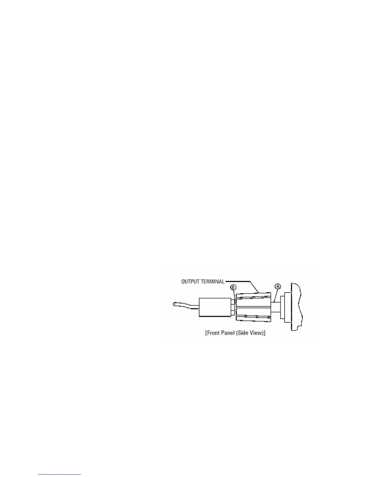
General Measurement Techniques
To achieve best results when measuring load regulation, peak to
peak voltage, and transient response time of the power supply,
measuring devices must be connected through the hole in the
neck of the binding post at (A) while the load resistor is plugged
into the front of the output terminals at (B). A measurement
made across the load includes the impedance of the leads to the
load. The impedance of the load leads can easily be several
orders of the magnitude greater than the power supply
impedance and thus invalidate the measurement. To avoid
mutual coupling effects, each measuring device must be
connected directly to the output terminals by separate pairs of
leads.
Figure 5-3 General Measurement