17
DIP SWITCH SETTINGS: TENANT SECTION AND MAIN SECTION
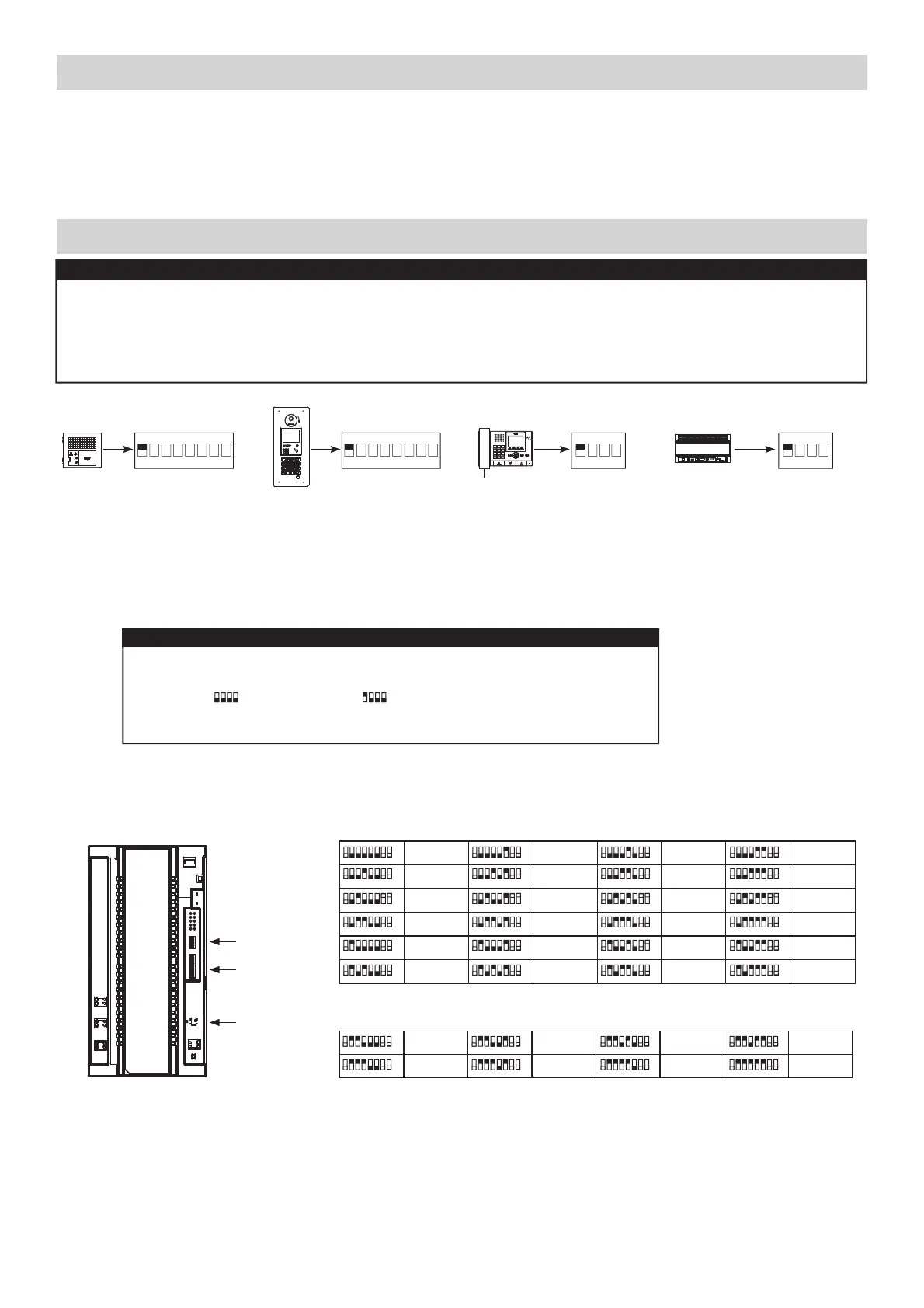
Each GT-MCX must be given a unique section ID and IP address. The section ID and IP address of each GT-MCX
will be determined by turning off DHCP and the SW2 dip switch setting. The IP address of the GT-MCX will be
192.168.1.50 + the ID number.
Example: 192.168.1.50 + ID 1 = 192.168.1.51
192.168.1.50 + ID 25 = 192.168.1.75
Step 1: Set SW3 dip switch 1 to ON to turn off DHCP.
Step 2: Set the SW2 dip switches 2-6 to the desired section ID based on the section type (see chart below).
SW3
(default)
4321
SW3
(DHCP Off)
4321
Step 3: Set Power switch to ON or cycle power when done.
SW2
SW3
25 26 27 28
29 30 31 32
Dip Switch ID Dip Switch ID Dip Switch IDDip Switch ID
ID’s 25-32: Main Sections
87654321
87654321
87654321
87654321
87654321
87654321
87654321
87654321
1234
5678
9101112
13 14 15 16
17 18 19 20
21 22 23 24
Dip Switch ID Dip Switch ID Dip Switch IDDip Switch ID
ID’s 1-24: Tenant Sections
87654321
87654321
87654321
87654321
87654321
87654321
87654321
87654321
87654321
87654321
87654321
87654321
87654321
87654321
87654321
87654321
87654321
87654321
87654321
87654321
87654321
87654321
87654321
87654321
Power switch
ON/OFF
GT-MCX
GT-MCX: NETWORK ADAPTOR
The GT-MCX connects a GT system to a network, allowing the system to be remotely programmed or multiple GT
systems to be tied together. When used for multiple systems, each system now becomes known as a section and
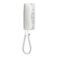
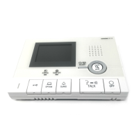
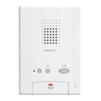
requires its own GT-MCX. There are two types of sections; the tenant section and the main section. A tenant section
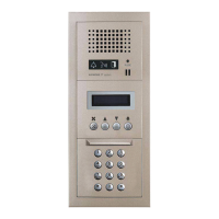
can contain tenant stations, entrance stations, and guard stations. A main section can contain the GT-DMB(-N, -LVN)
entrance stations and GT-MKB-N guard stations only.
Note: Main sections can call to tenant sections but tenant sections cannot call to other tenant sections.
When the GT-MCX is included in the system, it will occupy ID#1 for both the entrance stations and guard stations.
Set the entrance stations and guard stations in the system starting with ID#2. Refer to page 6 for ID settings. If the dip
switches are not set correctly on the entrance stations and guard stations, you will not be able to upload any settings.
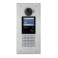
The entrance stations, guard stations, and the GT-BCXB-N expansion adaptor must be set to multi-building mode
when including the GT-MCX network adaptor. Set the switches as shown below per station.
ON
1
SW2 on GT-DB(-V, -VN)
ON
1
SW1 on GT-DMB(-N, -LVN)
ON
1
SW2 on GT-MKB-N
ON
1
SW2 on GT-BCXB-N
1
4
GHI
7
PQRS
#0
ABC
JKL
TUV
5
8
2
6
9
WXYZ
MNO
3
DEF
1
4
GHI
7
PQRS
#0
ABC
JKL
TUV
5
8
2
6
9
WXYZ
MNO
3
DEF
IMPORTANT
IMPORTANT

 Loading...