*DP
CN1
CN2
CN2
CN1
CN1
CN1
R1
R2
+
-
+
-
R1 R2R1 R2
CN1
CN1
CN100
CN100
+
-
+
-
ELC
ELM
ELB
PT
Mag
Lock
ELC
ELM
ELB
PT
R1 R2
IN
R1 R2
OUT
R1 R2
IN
R1 R2
OUT
R1 R2
IN
R1 R2
OUT
R1 R2
IN
R1 R2
OUT
R1 R2
IN
R1 R2
OUT
R1 R2
IN
R1 R2
OUT
R1 R2
IN
R1 R2
OUT
R1 R2
IN
R1 R2
OUT
R1 R2
IN
R1 R2
OUT
R1 R2
IN
R1 R2
OUT
R1 R2
IN
R1 R2
OUT
PS24
PS24
GT-BC
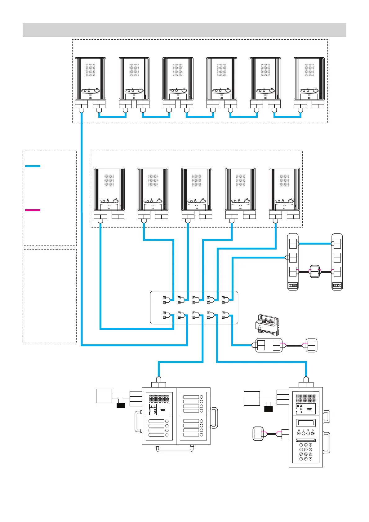
Loop Wiring Method
Max. of 25 stations per loop / trunk
Homerun Wiring Method
* Distribution Point:
(GTW-DP) Available in N.
America. (GFC) Available
in Europe. This can be
any device that parallels
or commons the R1 / R2
connection. (Terminal
strip, punch down block,
wire nuts, etc.)
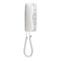
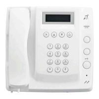
**Tenant stations shown
are the GT-1A. The
GT-1D tenant stations
can also be used
and wired in the same
manner.
Door
Strike
STANDARD SYSTEM WIRING: AUDIO ONLY
R1
R1
R2
R2
Max. wire distance from distribution point to any tenant is 980’ (300m).
Max. cumulative wire distance is 8200’ (2500m).
Refer to the GT Series Installation Manual for complete wire distance information.
WIRE TYPE
: Audio Line
20AWG (0.8mm)
2 Cond. Solid Non
Shielded
PE Insulated
: Video Line
18AWG (1.0 mm)
2 Cond. Solid Non
Shielded
PE Insulated
POWER
PS24
PS-2420UL
PS-2420
PS-2420S
PS-2420BF
PT
Power Transformer
(Use proper power
for the Strike or Mag
Lock being used.)
3
**
ELM: Make (N/O)
ELC: Common
ELB: Break (N/C)
+
-
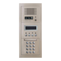
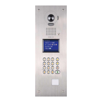
GT-MKB-N
+
-
GT-MKB-N
+
-
PS24
ON
123
4
#1
ON
123
4
#2
R1
R2
R1
R2
IN
OUT
R1
R2
R1
R2
OUT
IN
 Loading...