DIP SWITCH SETTINGS: ENTRANCE AND GUARD STATION ID SETTINGS
DIP SWITCH SETTINGS: ENTRANCE STATION
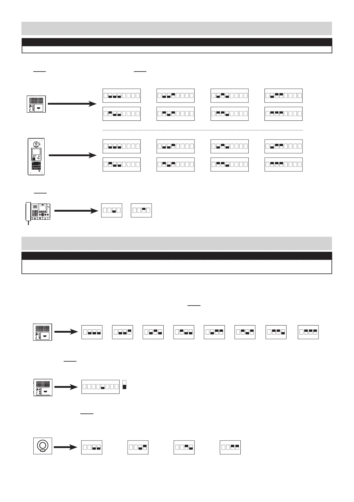
Entrance ID Setting:
Use SW2 on the GT-DB(-V, -VN) module or SW1 on the GT-DMB(-N, -LVN) entrance station to set the ID for each entry
panel. Switches 2 - 4 are used for this setting.
Guidance Language Setting:
The audio guidance is set to off (No Guidance) by default. Use SW3 on the GT-DB(-V, -VN) module to set the
appropriate language. Only switches 2, 3, & 4 are used for this setting.
ON
123
4
ON
123
4
ON
123
4
ON
123
4
ON
123
4
ON
123
4
ON
123
4
No Guidance English German DutchFrench Spanish Norwegian
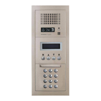
GT-DMB(-N, -LVN)
NOTE:
When using the GT-DMB(-N, -LVN), the settings listed below will be done via the keypad / display while in
programming mode. Refer to the GT Series Installation Manual for instructions.
Entrance Monitoring:
Use switch 5 of SW2 on the GT-DB(-V, -VN) module to enable / disable entrance monitoring. Default is “Monitoring not
allowed.” Enabling will allow video tenant stations to ‘call up’ the entrance station and monitor the door area.
5
Monitoring allowed
Monitoring not allowed (default)
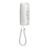
Camera View:
Use switches 3 & 4 of SW1 on the GT-VB module to set the camera view. The default setting is Zoom.
Zoom 3s>>Wide: Image starts zoomed and after 3 seconds goes wide.
Wide 3s>>Zoom: Image starts wide and after 3 seconds zooms.
GT-VB
ON
123
4
ON
123
4
ON
123
4
ON
123
4
ZOOM WIDE ZOOM 3s>>WIDE WIDE 3s>>ZOOM
(default)
(default)
SW2
SW1
ON
123
4
Tone
1
4
GHI
7
PQRS
#0
ABC
JKL
TUV
5
8
2
6
9
WXYZ
MNO
3
DEF
1
4
GHI
7
PQRS
#0
ABC
JKL
TUV
5
8
2
6
9
WXYZ
MNO
3
DEF
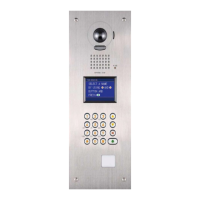
Guard ID Setting:
Use SW2 on the GT-MKB-N guard station to set the ID setting for each guard. Switch 3 is used for this setting.
SW2
GT-MKB-N
ON
23
4
1
ON
23
4
1
Make sure power is removed from the system before making any dip switch changes.
6 | GT Series Quick Start Guide
ID 1 / 3 ID 2 / 4
GT-DB(-V, -VN)
GT-DB(-V, -VN)
SW3
SW2
GT-DB(-V, -VN)
SW1
ON
23
4
ON
23
4
ON
23
4
ON
23
4
ON
23
4
ON
23
4
ON
23
4
ON
23
4
ID 1 / 9 ID 2 / 10 ID 3 / 11 ID 4 / 12
ID 5 / 13 ID 6 / 14 ID 7 / 15 ID 8 / 16
ON
23
4
ON
23
4
ON
23
4
ON
23
4
ON
23
4
ON
23
4
ON
23
4
ON
23
4
ON
5
ID 1 / 9 ID 2 / 10 ID 3 / 11 ID 4 / 12
ID 5 / 13 ID 6 / 14 ID 7 / 15 ID 8 / 16
NOTE:
When GT-MCX is included in the system, ID#1 cannot be used for entrance/guard stations.