*DP
CN1
CN1
CN100
CN100
CN2
CN2
ELC
ELM
ELB
PT
R1
R2
+
-
+
-
PS24
+
-
ELC
ELM
ELB
PT
A1 A2R1 R2
A1
A2
R1
R2
+
-
+
-
PS24
GT-BC
+
-
A1 A2 A1 A2 A1 A2 A1 A2
A1 A2
B1 B2 B1 B2 B1 B2 B1 B2 B1 B2 B1 B2
B1 B2 R1 R2
B1 B2 R1 R2
B1 B2 R1 R2
B1 B2 R1 R2
B1 B2 R1 R2
B1 B2 R1 R2
B1 B2 R1 R2
B1 B2 R1 R2
Max. of 25 stations
per loop. SW1 switch
must be set to A on last
station in the wire loop.
B1 B2 R1 R2
B1 B2 R1 R2
B1 B2 R1 R2
B1 B2 R1 R2
B1 B2 R1 R2
B1 B2 R1 R2B1 B2 R1 R2
B1 B2 R1 R2
Max. of 6 GT-4Zs per trunk. SW1 switch must be
set to A on last GT-4Z in the wire trunk. Each tenant
station homeruns to a GT-4Z and its SW1 switch
must be set to A.
GT-VBC
B1 B2 R1 R2 B1 B2
R1 R2
B1 B2 R1 R2 B1 B2 R1 R2 B1 B2 R1 R2
R1 R2B1 B2
OUT (1) OUT (2)
OUT (3) OUT (4)
IN
LINE OUT
SW1
A
B
GT-4Z
B1 B2 R1 R2 B1 B2 R1 R2
B1 B2 R1 R2 B1 B2 R1 R2 B1 B2 R1 R2
R1 R2B1 B2
OUT (1) OUT (2)
OUT (3) OUT (4)
IN
LINE OUT
SW1
A
B
GT-4Z
IN
OUT
IN
OUT
IN
OUT
IN
OUT
IN
IN
IN
IN
IN
IN
IN
IN
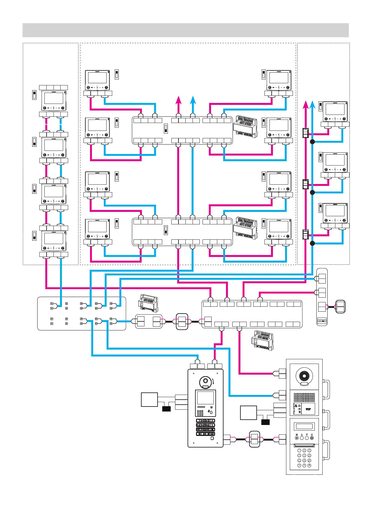
Loop Wiring Method Homerun Wiring Method
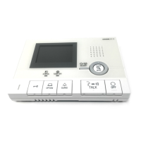
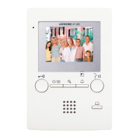
Tenant stations shown
are the GT-1C7(-L).
The GT-1M3(-L) and
GT-2C(-L) tenant stations
can also be used and wired
in the same manner.
Note: GT-2C(-L) requires
a separate PS-24 power
supply.
Mag
Lock
Door
Strike
STANDARD SYSTEM WIRING: AUDIO / VIDEO
R1
R1
R2
R2
A
B
A
B
A
B
SW1
A
B
A
B
A
B
A
B
A
B
A
B
A
B
A
B
A
B
4 | GT Series Quick Start Guide
To additional units
**
**
SW1
T-Tap Wiring Method
Max. of 25 stations
per trunk with GT-1Z.
SW1 switch must
be set to A on each
tenant station.
B1 B2 R1 R2
B1 B2 R1 R2
B1 B2 R1 R2
A
B
A
B
A
B
SW1
GT-1ZGT-1ZGT-1Z
LINE IN LINE IN LINE INLINE OUT LINE OUT LINE OUT
To
Additional
units
OUT
OUT
OUT
IN
IN
IN
SW1
SW1
SW1
SW1
SW1
SW1
SW1
SW1
SW1
SW1
SW1
SW1
ELM: Make (N/O)
ELC: Common
ELB: Break (N/C)
*
Distribution Point:
(GTW-DP) Available in N.
America. (GFC) Available
in Europe. This can be
any device that parallels
or commons the R1 / R2
connection. (Terminal strip,
punch down block, wire
nuts, etc.)
Use Sxx (S1-S48) for link ID settings for
addressing tenants via dip switch method in a
standard system (refer to page 8 for settings).
+
-
GT-MKB-N
+
-
PS24
ON
123
4
#1
IN
IN
R1
R2
B1
B2
 Loading...