5
A1
A2
A1
A2
A1
A2
A1
A2
A1
A2
A1
A2
A1
A2
A1
A2
B1
B2
B1
B2
B1
B2
B1
B2
COMMON 1
SUB 1
SUB 2
A1
A2
A1
A2
~
COMMON 2
CN2
+
-
COMMON 1
R1
R2
R1
R2
~
COMMON 2
CN1
R1
R2
R1
R2
~
R1
R2
SUB 1A
R1
R2
R1
R2
~
SUB 1B
R1
R2
R1
R2
~
SUB 2A
R1
R2
R1
R2
~
SUB 2B
R1
R2
R1
R2
~
GTW-LC
USB
GT-VBX
GT-BCXB-N
A1
A2
A1
A2
A1
A2
A1
A2
R1
R2
R1
R2
R1
R2
R1
R2
ID1 ID3ID2 ID4
R1
R2
R1
R2
+
-
OUT
IN
GT-MKB-N
R1
R2
R1
R2
+
-
IN
OUT
GT-MKB-N
+
-
PS24
ON
123
4
#2
ON
123
4
#1
Connection
for video
entrance
modules 9-16
{
{
Connection
for audio
entrance
modules 9-16
R1
R2
+
-
GT-BC
+
-
PS24
+
-
A1
A2
A1
A2
A1
A2
A1
A2
A1
A2
B1
B2
B1
B2
B1
B2
B1
B2
B1
B2
B1
B2
+
-
EXP STD
+
-
R1
R2
*DP
PS24
GT-BC
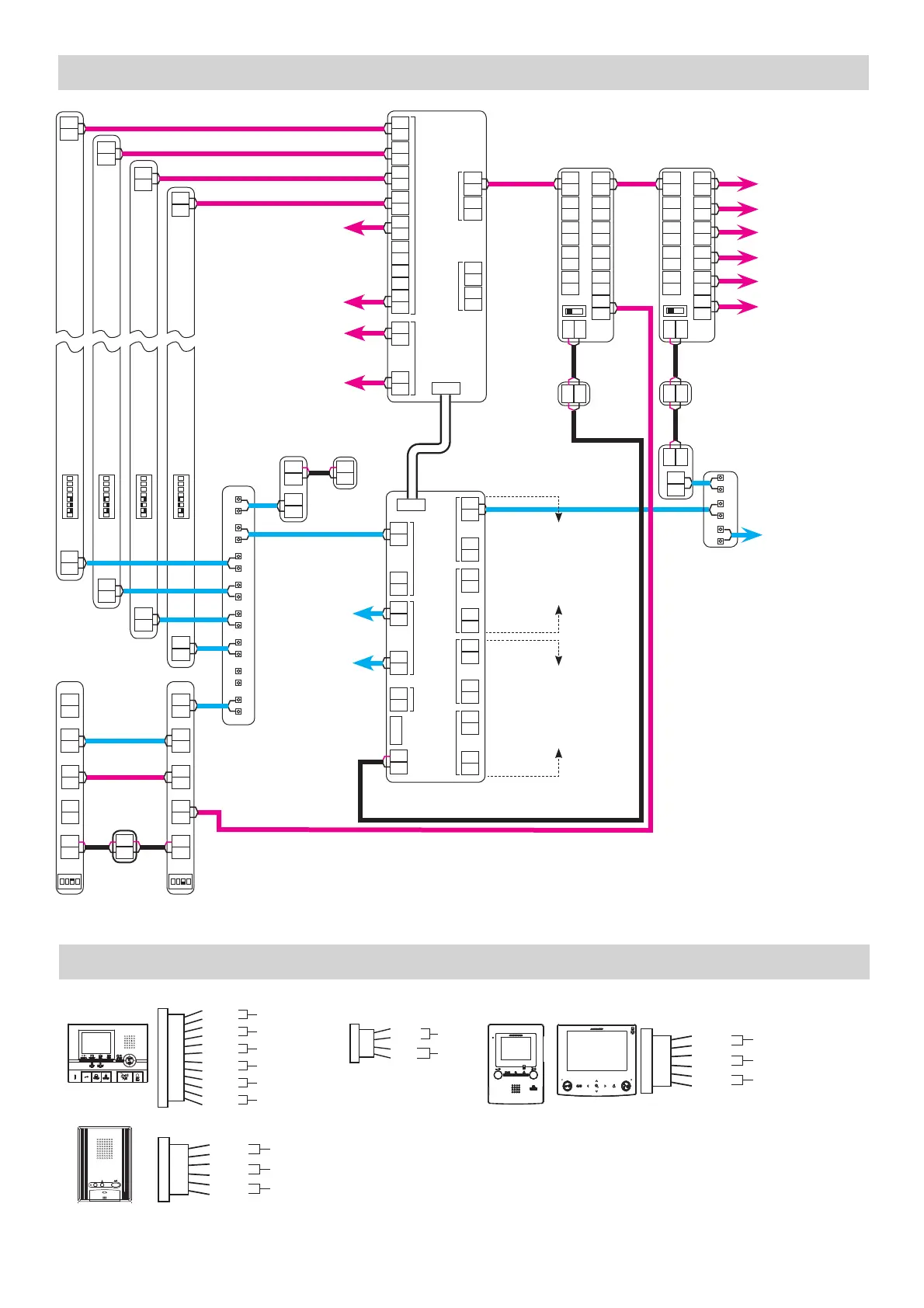
Video outputs to
tenant stations
and / or GT-4Z or
GT-1Z units. Max.
of 25 tenants per
trunk and 125
total tenants per
GT-VBC.
Audio output to
tenant stations
and / or GT-4Z
units. Max. of
25 tenants per
trunk and 125
total tenants
per GT-BC.
GT-VB
GT-DB(-V,-VN)
EXPANDED SYSTEM WIRING
OPTION CONNECTOR WIRING: TENANT STATIONS
GT-VBC
K
KE
RY
RY
SW
SW
S1
S1E
S2
S2E
S3
S3E
Emergency alarm
( Brn )
( Red )
Ext. Signaling (GT-RY)
( Blu )
( Wht )
Option contact output
( Gry )
( Blk )
Security/Utility input 1
( Org )
( Blk )
Security/Utility input 2
( Yel )
( Blk )
Security/Utility input 3
( Pur )
( Blk )
12-pin option connector
DC
DC
RYC
RYC
SW
SW
Doctor call (Automatic entry)
(
Ye l
)
(
Org )
External Signaling (GT-RY)
( Blu )
( Wht )
Option contact output
( Gry )
( Blk )
Option connector
DC
DC
RY
RY
SW
SW
Doctor call (Automatic entry)
( Yel )
( Org )
External Signaling (GT-RY)
( Blu )
( Wht )
Option contact output
( Gry )
( Blk )
Option connector
GT-2C(-L)
GT-1A
GT-1M3(-L)
Only the option connectors for the GT-2C(-L), GT-1C7(-L),
GT-1M3(-L), and GT-1A are shown here. For information
on other tenant and guard station option connectors and for
technical specifi cations for each connection, refer to the GT
Series Installation Manual.
* Distribution Point:
(GTW-DP)
Available in N.
America. (GFC) Available in
Europe. This can be any device
that parallels or commons the
R1 / R2 connection. (Terminal
strip, punch down block, wire
nuts, etc.)
V+
V
-
( Brn )
( Red )
( Org )
( Yel )
Video out
Video Out
Notication
4-pin option connector
(not included)
GT-1C7(-L)
Connection
for video
entrance
modules 5-8
{
+
-
A1
A2
A1
A2
A1
A2
A1
A2
A1
A2
B1
B2
B1
B2
B1
B2
B1
B2
B1
B2
B1
B2
EXP STD
GT-VBC
+
-
PS24
B1
B2
B1
B2
OUT
IN
B1
B2
B1
B2
IN
OUT
*DP
ON
23
4
ON
23
4
ON
23
4
ON
23
4
Use Axxx (A1-A250) for link
ID settings for addressing
tenants on Sub 1A/1B via
the dip switch method in an
expanded system.
Use Bxxx (B251-B500)
for link ID settings for
addressing tenants on Sub
2A/2B via the dip switch
method in an expanded
system.

 Loading...