Begin System Installation
Connection can be made directly to a facility's alarm reporting system. If there is more than one
BDS at the same location and only one set of contacts can be monitored, the alarm contacts
can be wired in parallel. Refer to BDS–1193–B986.
The plus and minus remote reset input contacts are on the BDS–40 Base Unit rear panel.
Connecting a +12VDC/GND signal to the reset input contacts will reset alarms for all strings. If
there is more than one BDS at the same location, and only one set of contacts is available for
reset, these inputs can be wired in parallel.
NOTE:
The ground connection is the most right connection in the 8 eight position connector.
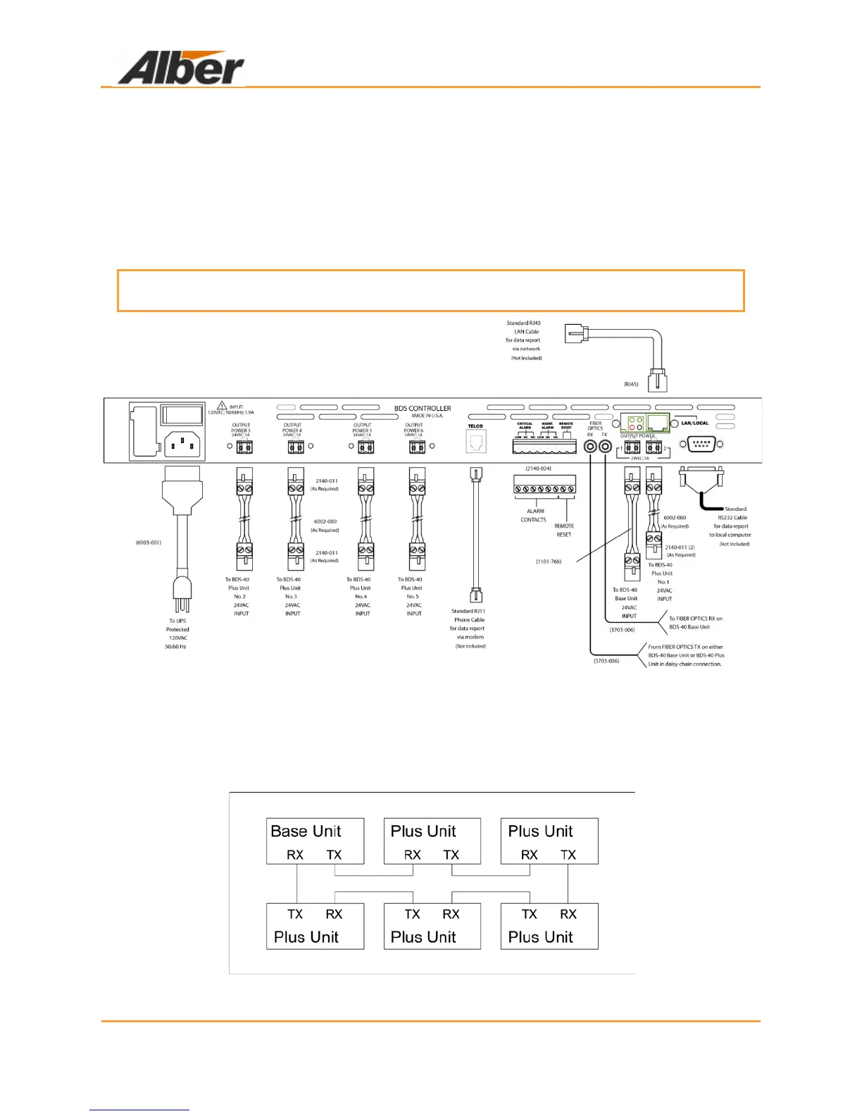
Figure 44. Snapshot BDS–1193–B986
7.3 Base To Plus Unit Fiber Optic Connection
When using a BDS–40 Base unit with one or more BDS–40 Plus units, connect the Base and
Plus units as shown in the following figure. Use Application Details Drawing BDS–5274–B1054
as an example.
Figure 45. Base to Plus Unit Connection