Managing OmniSwitch 6450 Stacks Slot Numbering
OmniSwitch 6450 Hardware Users Guide September 2015 page 7-21
Dynamic Slot Number Assignment
Dynamic slot number assignment occurs when there are no boot.slot.cfg files present in the switches’
/flash directories. This is the case for new, “out of the box,” switches that have not been previously
booted.
When a brand new stack (or stack with no boot.slot.cfg files) is booted, the system software automati-
cally detects the module with the lowest MAC address. This module is assigned the primary management
role (see page 7-4) and, by default, is given the slot number 1. The module connected to the primary’s
stacking port A is automatically assigned the secondary management role and given the slot number 2.
As the other modules in the stack become operational, they are assigned idle roles and are automatically
assigned unique slot numbers. The slot numbering for idle modules is determined by each module’s physi-
cal location in the stack. Refer to the diagrams below for more information on dynamic slot numbering.
Note. As the slot numbers are dynamically assigned, boot.slot.cfg files are auto-generated in the /flash
directory of each switch. When modules are subsequently booted, each switch reads its slot number
assignment from this file and comes up accordingly.
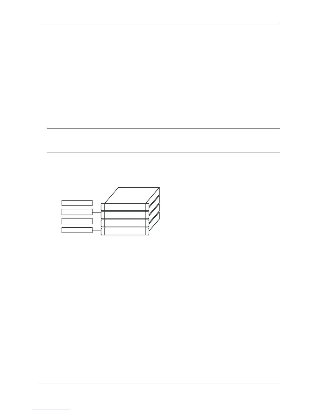
Dynamic Slot Numbering Example 1
Slot 1 - Primary
Slot 2 - Secondary
Slot 3 - Idle
In this example, the fourth switch from the top is
elected the primary management module for the
stack. (It can be assumed that this switch has the low-
est MAC address in the stack.) This switch is auto-
matically assigned slot number 1.
The switch immediately below is connected to the pri-
mary switch’s stacking port A and, as a result, is
assigned the secondary management role and given
slot number 2.
The system software allows the switch immediately
below slot 2 to have the next slot number preference. It
is assigned an idle role and given the slot number 3. The
switch immediately below slot 3 is given the slot number
4, and so on. When the bottom of the stack is reached,
the slot numbering sequence resumes at the top of the
stack, as shown. This helps ensure a more ordered and
manageable stack topology.
Slot 4 - Idle
 Loading...