Operation Mode
Stand AloneAssociated UA Set
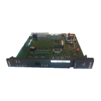
To configure the V24/CTI Interface Module, open the device with the 2 screws located under the
module.
If the jumper is positioned for "stand-alone" operation, an associated set cannot work.
If the jumper is positioned for "associated UA set" operation, the associated set is mandatory, the
Interface Module cannot work without it.
4.10.3 External connections
4.10.3.1 V24/CTI Interface Module Connection
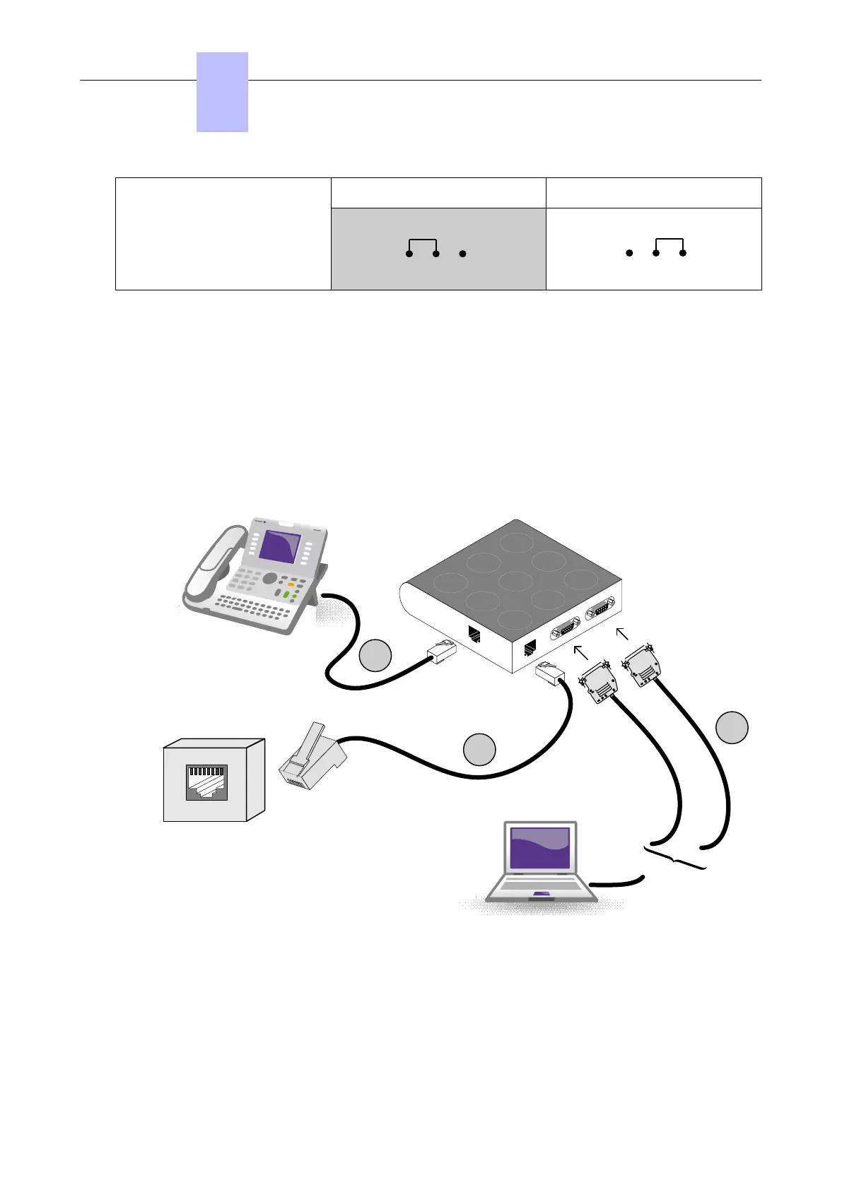
The V24/CTI Interface Module is connected as follows:
1
2
3
V24/CTI PC
V24/CTI
Interface Module
Wall Socket
(to the PCX)
UA line
or
CTI
V24
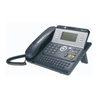
9 Series Set
(Optional)
UA line
Figure 4.11: V24/CTI Interface Module Connection
The V24/CTI Interface Module is connected to:
1. The digital set 3 m maximum length ( RJ11/RJ11 cable)
2. The PCX via a wall socket and a distributor frame
3. The CTI or V24 terminal:
• V24: 3m maximum length
Chapter
4
Installation and Cabling
3EH21123USAA - Ed. 01 - April 2017 - Installation Manual 110/207