8 7 6 5 4 3 2 1
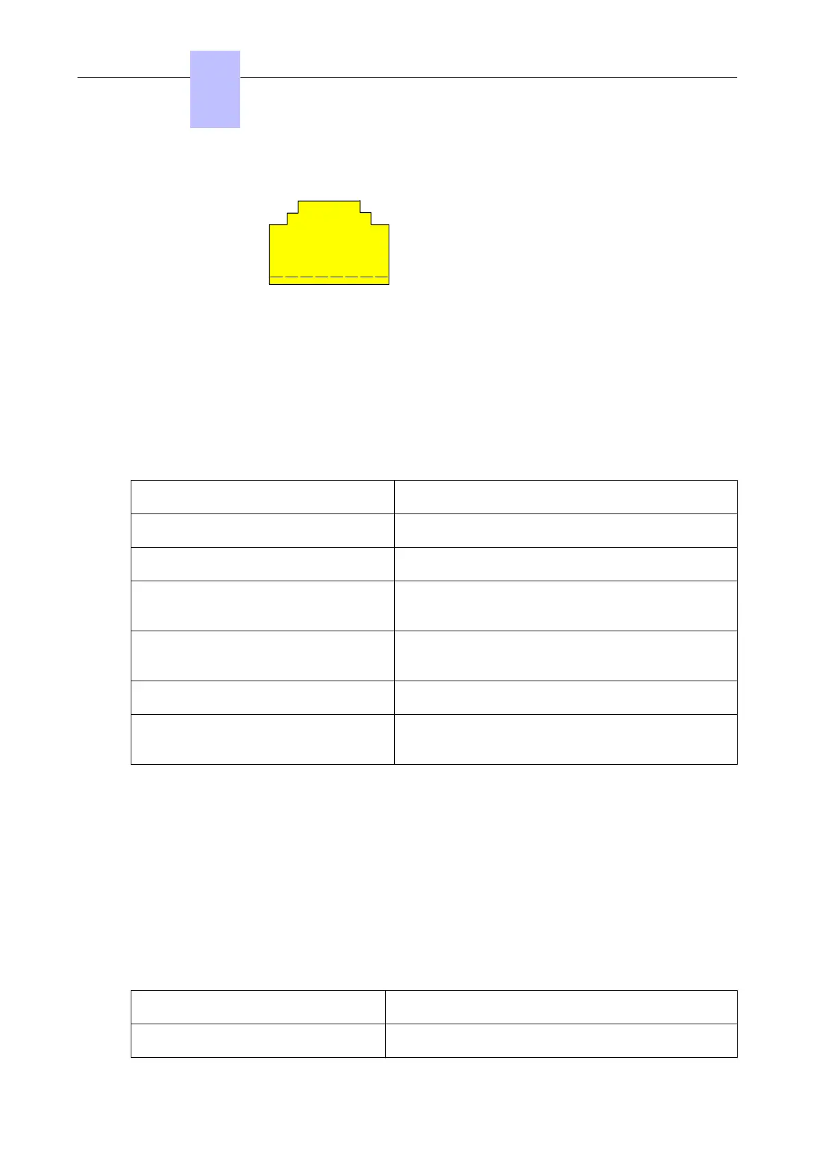
DAP RJ45 Socket
8=
7=
6=
5=
4=
3=
2=
1=
RTN (0 Volt) power
100 Base-T RX-
+48 Volt Power
+48 Volt power
100 Base-T RX +
100 Base- T TX-
100 Base-T TX+
RTN (0 Volt) power
Figure 4.24: Pin Layout Ethernet Connector RJ45 on the DAP
The IP-DECT base station access points are fitted with 2 LEDs that provide information about the
status.
• Top LED – Yellow
This LED represents the status of the IP-DECT base station.
LED Status (Top LED, Yellow) Meaning
Off No power
0,5 sec. On - 0,5 sec. Off Loading software/firmware
Short flash every 0,25 seconds IP Network error (not connected, no DHCP/TFTP serv-
er, no DAP Controller
Fast blink DAP operational, but trying to synchronize to another
DAP
Continuous fast blink Hardware error
Steady On DAP operational (and synchronized to other DAP or is
the synchronization master)
Note:
The colour of the top LED can be different depending on the operational mode.
• Normal (single band) mode
In the normal single band mode, the top LED will be Yellow.
• Dual Band
Mode In Dual Band mode, the LED colour shows the operational frequency:
• Green: Europe/International
• Red: North America / USA
• Lower LED – Red/Green
This LED is used to indicate the start-up and network status.
LED Status (lower LED, Red/Green) Meaning
RED Steady on Power but FPGA starting up
Chapter
4
Installation and Cabling
3EH21123USAA - Ed. 01 - April 2017 - Installation Manual 135/207