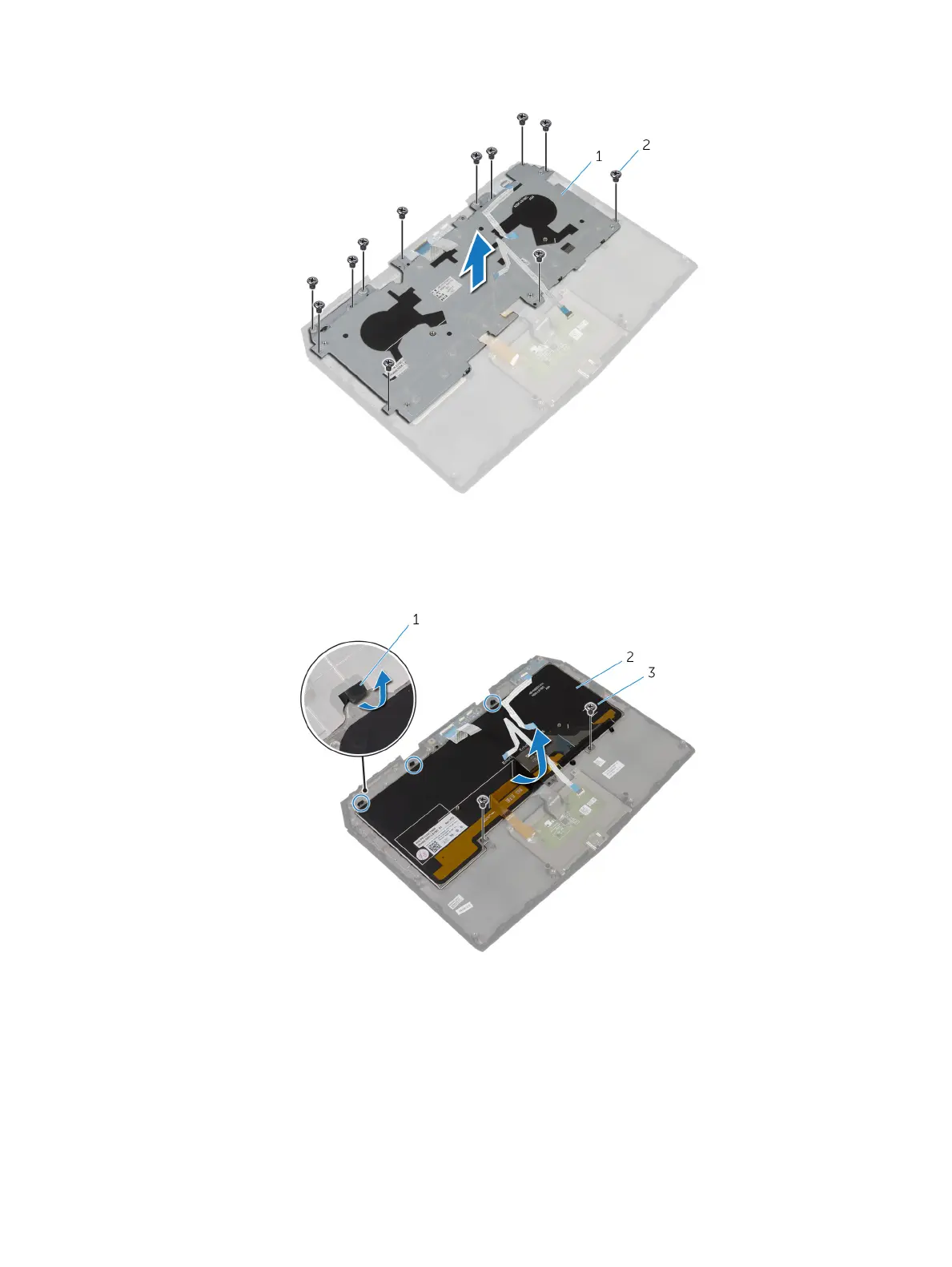
3 Remove the screws that secure the keyboard bracket to the palm-rest assembly.
1 keyboard bracket 2 screws (12)
4 Lift the keyboard bracket o the palm-rest assembly.
5 Remove the screws that secure the keyboard to the palm-rest assembly.
6 Slide and lift the keyboard, along with the cables, o the palm-rest assembly.
1 tabs (3) 2 keyboard
3 screws (2)
31