KINTEX UltraScale+ FPGA Board AXKU040 User Manual
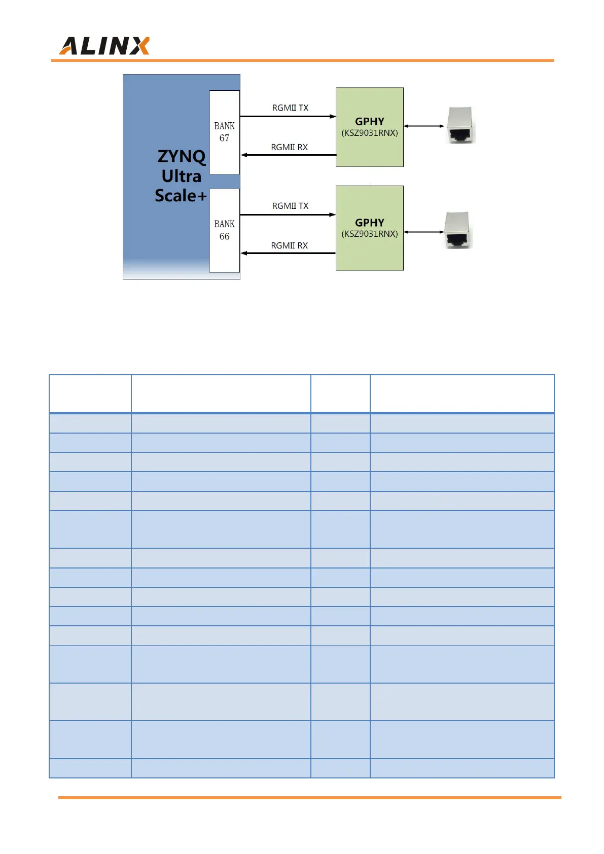
Figure 9-1: FPGA Chip and GPHY connection diagram
The 1
st
Gigabit Ethernet interface pin assignments are as follows:
IO_L4N_T0U_N7_DBC_AD7N_66
Ethernet 1 Transmit Clock
Ethernet 1 Transmit Data bit0
Ethernet 1 Transmit Data bit1
Ethernet 1 Transmit Data bit2
IO_L4P_T0U_N6_DBC_AD7P_66
Ethernet 1 Transmit Data bit3
Ethernet 1 Transmit Enable
Signal
Ethernet 1 Receive Data Bit0
Ethernet 1 Receive Data Bit1
Ethernet 1 Receive Data Bit2
Ethernet 1 Receive Data Bit3
Ethernet 1 Receive Data Enable
Signal
Ethernet 1 MDIO Management
Clock
Ethernet 1 MDIO Management
Data