2–4 Configuring the Module
Configuring the module
As you configure your module, you should complete the I/O image
table. First, size the I/O using switch SW3. Next, set the rack address
using switch SW1. Finally, select the starting group, last rack setting,
fault action, and baud rate using switch SW2. For more information
on the I/O image table, refer to the example below and Chapter 4.
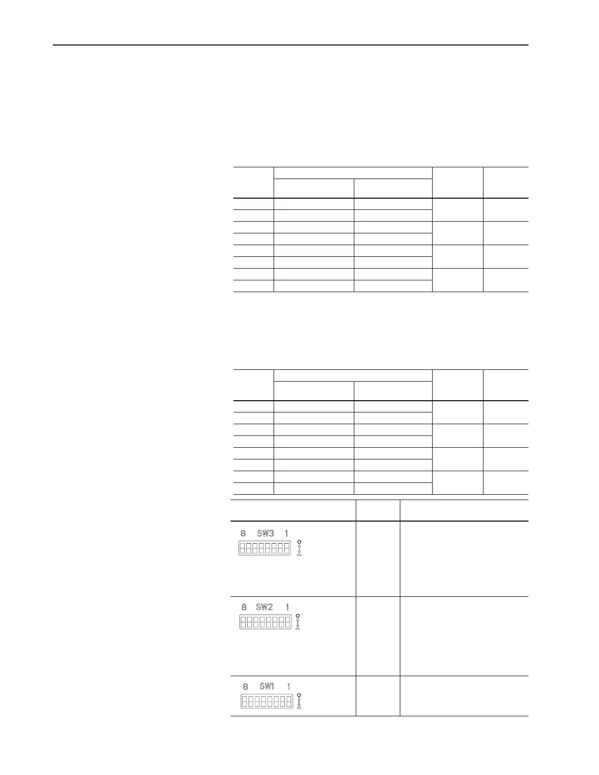
I/O Image Table
Example I/O Image Table
In this example, we use the factory-default settings. We use rack 2,
and record it as our address. Because we are using a full rack, we use
starting group 0, so block transfer starts at word 0.
Remote
I/O
Address
Reserved For: Minimum
Required
Rack Size
Starting
GroupOutput Image Input Image
1/4 Rack 0, 2, 4, or 6
1/2 Rack 0, 2, or 4
3/4 Rack 0 or 2
Full Rack 0 only
Remote
I/O
Address
Reserved For: Minimum
Required
Rack Size
Starting
GroupOutput Image Input Image
020 Block Transfer Block Transfer 1/4 Rack 0, 2, 4, or 6
021 Logic Command Logic Status
022 Reference Feedback 1/2 Rack 0, 2, or 4
023 Datalink A Datalink A
024 Datalink A Datalink A 3/4 Rack 0 or 2
025 Datalink B Datalink B
026 Datalink B Datalink B Full Rack 0 only
027
Switch
Settings
8 ---> 1 Description
00011111 Block transfer is enabled.
Logic command/status is enabled.
Reference/feedback is enabled.
Datalink A is enabled.
Datalink B is enabled.
Truncate last datalink is disabled.
00011011 Starting group is 0.
This is not the last rack.
Drive will fault when communications
are disrupted, and it will hold last state
when the controller is placed in
program/reset/test.
Remote I/O baud rate is 57.6K.
10111100 Rack address is 2.
Off = 0
On = 1
Off = 0
On = 1
Off = 0
On = 1
Artisan Scientific - Quality Instrumentation ... Guaranteed | (888) 88-SOURCE | www.artisan-scientific.com
 Loading...


