Configuring the Module 2–9
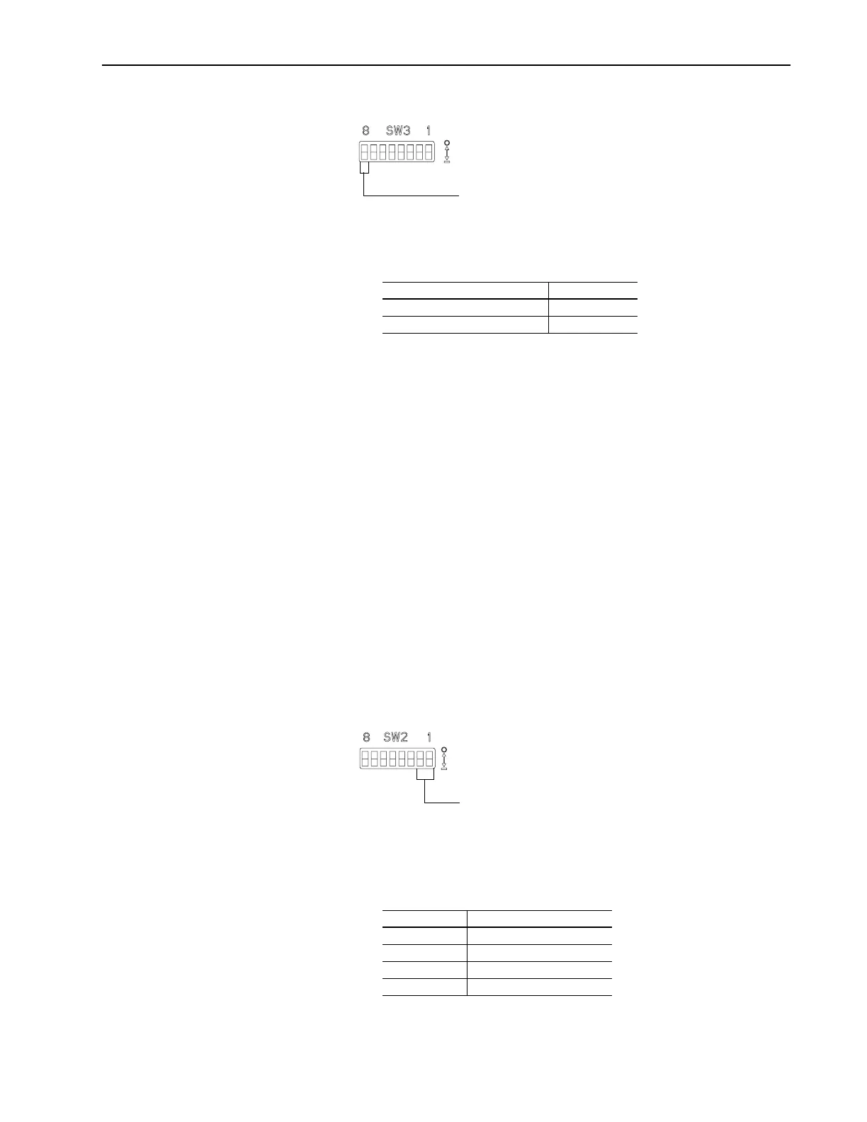
Figure 2.7 Truncate Last Datalink Switch
To set the truncate last datalink feature, you need to:
1. Refer to the following table to determine the setting for SW 3.8:
2. Slide the switch to its appropriate position.
3. If the switch is enabled, cross out the second module group
(word) of the last datalink in your I/O image table on page 2–4.
Settings take effect when a module or board first receives power.
When you change a setting, you must remove and then reapply power
for the new setting to take effect.
Setting Switches on SW2
Setting the Starting Group
SW 2.2 and SW 2.1 set the starting group. A starting group is the
word in a rack at which the group starts. The starting group depends
on the rack size. To determine the starting group, you must set the
switches on SW3 and calculate the rack size. A full rack is 8 words.
For example, if we enabled the switches for Logic Command/Status,
Reference/Feedback, and datalink A, we use 4 words in the rack, so
we need a 1/2 rack. Using the table below as a guide, we could set the
starting group for word 0, 2, or 4 for our example.
Figure 2.8 Starting Group Switches
To edit the starting group, you need to:
1. Refer to the following table to determine starting groups that you
can use:
Duplicate Message Detection SW 3.8
Disable 0
Enable 1
Off = 0
On = 1
Use SW 3.8 for truncating the
last datalink.
Rack Size Starting Group
1/4 0, 2, 4, or 6
1/2 0, 2, or 4
3/4 0 or 2
Full 0
Off = 0
On = 1
Use SW 2.2 and SW 2.1
for setting the starting group.
Artisan Scientific - Quality Instrumentation ... Guaranteed | (888) 88-SOURCE | www.artisan-scientific.com
 Loading...


