Chapter
2
Configuring the Module
Chapter Objectives
Chapter 2 provides instructions and information for configuring the
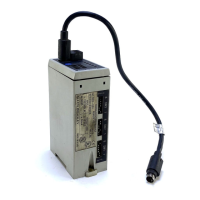
Remote I/O communications module (1203-GD1, 1203-GK1, or
1336-GM1). In this chapter, you will read about the following:
• Factory-default settings.
• Recording the I/O image table.
• Configuring the module.
Important:
The communications module is not compatible with
complementary I/O configurations because it uses both
output and input image words for proper product control.
Safety Precautions and
Important Information
Please observe the following safety precautions:
Important:
Due to an anomaly in firmware release 4.01, Remote I/O
modules that are used only for block transfer messages
require the following configuration: switches for block
transfer and reference/feedback should both be enabled
(SW 3.1 and SW 3.3 are ON. SW 3.2 and SW 3.4 through
3.8 are OFF).
This configuration prevents a fault on power up. It does not
affect rack I/O allocation or the ladder logic program
because it still fits within 1/4 rack I/O space. The drive will,
however, generate a serial fault if the communications
module is disconnected or loses power.
!
ATTENTION: Hazard of equipment damage exists. When
you make changes to the switch settings, use a blunt, pointed
instrument. Do not use a pencil or pen.
!
ATTENTION: Hazard of injury or equipment damage
exists. Failure to check connections and switch settings for
compatibility with your application could result in
unintended or undesirable operation. Verify the
configuration is correct for your application.
!
ATTENTION: Hazard of injury or equipment damage
exists. Unintended or incorrect machine motion can result
from the initial configuration. When a system is configured
for the first time, the motor must be disconnected from the
machine or process during initial system testing.
Artisan Scientific - Quality Instrumentation ... Guaranteed | (888) 88-SOURCE | www.artisan-scientific.com

 Loading...


