Configuring the Module 2–13
Setting Switches on SW1
Setting the Rack Address
DIP switches 8 through 3 on SW 1 set the rack address for the
Remote I/O module. Each Remote I/O device must have a rack
address that the controller can recognize. Each rack contains 8 words.
Important:
When using a PLC-2 family processor, add 1 to the rack
number set on the Remote I/O module DIP switches to
your PLC code. The PLC-2 cannot have a Remote I/O rack
numbered zero, so add a value of one to the rack number
value when writing your PLC code.
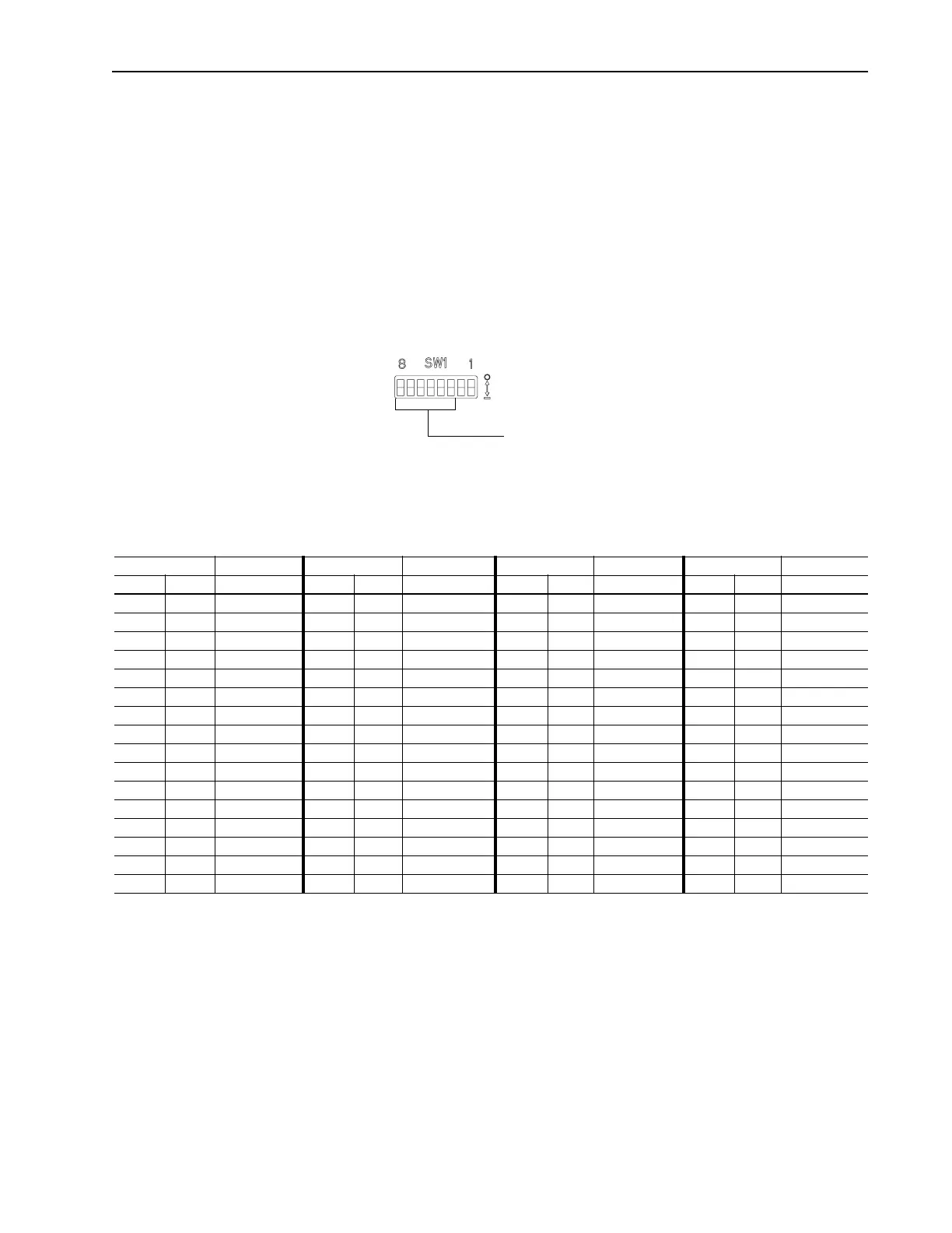
Figure 2.12 Rack Address Switches
To edit the rack address, you need to:
1. Refer to the following table to determine the settings for SW1.8
through SW1.3:
Important:
Not all controllers support all of these node addresses.
Refer to the documentation for your controller. The
maximum number of devices on a Remote I/O link is 32.
2. Slide the switches to their appropriate positions.
Settings take effect when a module or board first receives power.
When you change a setting, you must remove and then reapply power
for the new setting to take effect.
Off = 0
On = 1
Use DIP switches 8 through 3 on SW1
for setting the module address.
Address Switch Setting Address Switch Setting Address Switch Setting Address Switch Setting
Decimal Octal 8 <---- 3 Decimal Octal 8 <---- 3 Decimal Octal 8 <---- 3 Decimal Octal 8 <---- 3
0 0 111111 16 20 111101 32 40 111110 48 60 111100
1 1 011111 17 21 011101 33 41 011110 49 61 011100
2 2 101111 18 22 101101 34 42 101110 50 62 101100
3 3 001111 19 23 001101 35 43 001110 51 63 001100
4 4 110111 20 24 110101 36 44 110110 52 64 110100
5 5 010111 21 25 010101 37 45 010110 53 65 010100
6 6 100111 22 26 100101 38 46 100110 54 66 100100
7 7 000111 23 27 000101 39 47 000110 55 67 000100
8 10 111011 24 30 111001 40 50 111010 56 70 111000
9 11 011011 25 31 011001 41 51 011010 57 71 011000
10 12 101011 26 32 101001 42 52 101010 58 72 101000
11 13 001011 27 33 001001 43 53 001010 59 73 001000
12 14 110011 28 34 110001 44 54 110010 60 74 110000
13 15 010011 29 35 010001 45 55 010010 61 75 010000
14 16 100011 30 36 100001 46 56 100010 62 76 100000
15 17 000011 31 37 000001 47 57 000010 63 77 000000
Artisan Scientific - Quality Instrumentation ... Guaranteed | (888) 88-SOURCE | www.artisan-scientific.com
 Loading...


