60 Rockwell Automation Publication 1791ES-UM001G-EN-P - November 2016
Chapter 3 Install the Module
I/O Connections
This section describes the I/O connectors and recommended cables.
Table 18 - I/O Connector Pin Description
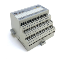
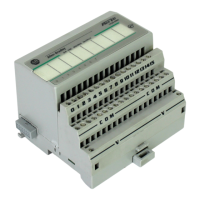
Figure 22 - I/O Connector Positions
Pin No. Input Signal I/O Connector Bipolar Output
Signal
Sourcing Output
Signal
1 Test out n+1 Output +24V DC
power
Output +24V DC
power
2 Input n+1 Output n+1 (N)
(sinking)
Output n+1
3 Input common Output power
common
Output power
common
4 Input n Output n (P)
(sourcing)
Output n
5 Test out n Output power
common
Output power
common
Case No connect No connect No connect
Table 19 - Terminal Positions
Terminal 1732ES-IB12XOBV2 1732ES-IB12XOB4 1732ES-IB16 1732ES-IB8XOBV4 1732ES-IB8XOB8
A-1 Test out 1 Test out 1 Test out 1 Test out 1 Test out 1
A-2 Safety input 1 Safety input 1 Safety input 1 Safety input 1 Safety input 1
A-3 Input common Input common Input common Input common Input common
A-4 Safety input 0 Safety input 0 Safety input 0 Safety input 0 Safety input 0
A-5 Test out 0 Test out 0 Test out 0 Test out 0 Test out 0
B-1 Test out 3 Test out 3 Test out 3 Test out 3 Test out 3
B-2 Safety input 3 Safety input 3 Safety input 3 Safety input 3 Safety input 3
B-3 Input common Input common Input common Input common Input common
B-4 Safety input 2 Safety input 2 Safety input 2 Safety input 2 Safety input 2
B-5 Test out 2 Test out 2 Test out 2 Test out 2 Test out 2
C-1 Test out 5 Test out 5 Test out 5 Test out 5 Test out 5
C-2 Safety input 5 Safety input 5 Safety input 5 Safety input 5 Safety input 5
C-3 Input common Input common Input common Input common Input common
C-4 Safety input 4 Safety input 4 Safety input 4 Safety input 4 Safety input 4

 Loading...


