1–3
Overview of FLEX I/O and your Remote I/O Adapter Module
Publication
17946.5.3 - May 1996
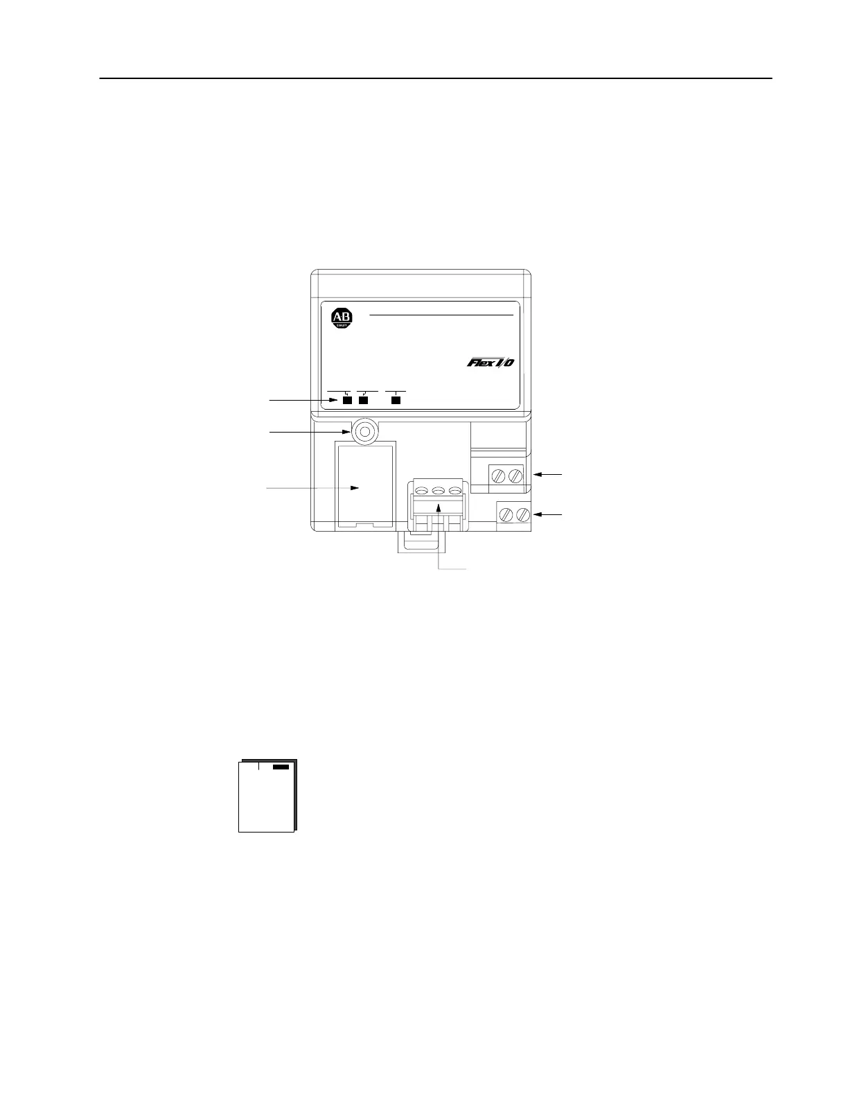
The adapter module consists of the following major components:
• diagnostic indicators
• reset pushbutton
• remote I/O wiring connections
• 24V dc power wiring connections
• address/group switch assemblies
Diagnostic Indicators
Reset Pushbutton
+24V dc Wiring Connections
24V dc Common Wiring Connections
Remote I/O Wiring Connections (connector part no. 942029-03)
Address/Group Switches
AllenBradley
24
VDC
POWER SUPPL
Y
RIO ADAPTER
1794-ASB
ADAPTER
ACTIVE FAULT
LOCAL
FAULT
Diagnostic Indicators
Diagnostic indicators are located on the front panel of the adapter
module. They show both normal operation and error conditions in
your remote I/O system. The indicators are:
• Adapter ACTIVE (green)
• Adapter FAULT (red)
• LOCAL FAULT (red)
A complete description of the diagnostic indicators and how to use
them for troubleshooting is explained in chapter 4.
Hardware Components

 Loading...


