3–15
Communicating with FLEX I/O Modules
Publication
17946.5.3 - May 1996
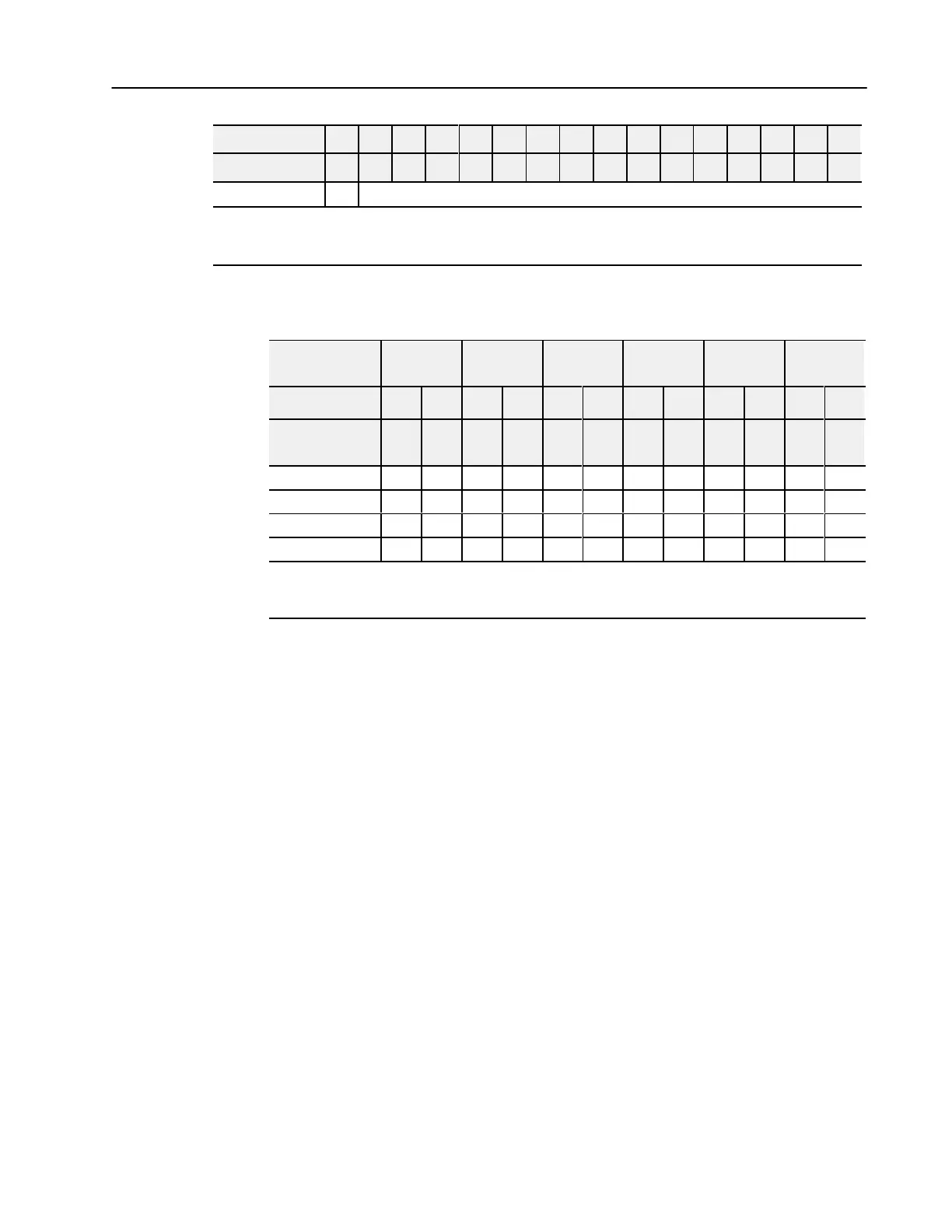
00010203040506070809101112131415Word/Dec. Bit
00010203040506071011121314151617Word/Octal Bit
Word 7 S Safe State Value - Output Channel 1
Where: S
= Sign bit (in 2'
s complement)
M = Multiplex control
C = Configure select bit
F = Full range bit
Range Selection Bits for the 1794-IE4XOE2/B Analog
Combo Module
Channel No. Input
Channel 0
Input
Channel 1
Input
Channel 2
Input
Channel 3
Output
Channel 0
Output
Channel 1
F0 C0 F1 C1 F2 C2 F3 C3 F4 C4 F5 C5
Decimal Bits
(Octal Bits)
00
08
(10)
01
09
(11)
02
10
(12)
03
11
(13)
04
12
(14)
05
13
(15)
4-20mA 0 1 0 1 0 1 0 1 0 1 0 1
0-10V dc/0-20mA 1 0 1 0 1 0 1 0 1 0 1 0
10 to +10V dc 1 1 1 1 1 1 1 1 1 1 1 1
Off
1
0 0 0 0 0 0 0 0 0 0 0 0
C
= Configure select bit
F = Full range bit
1
When configured to of
f, individual channels will send 0V or 0mA on Series B modules. On Series A modules, 2V or 4mA is output
until the module is configured.

 Loading...


