2–6
Installing Your Remote I/O Adapter Module
Publication
17946.5.3 - May 1996
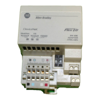
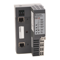
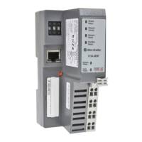
The remote I/O adapter module has two 8-position switch assemblies
which you set for:
• starting I/O group
• I/O rack number
• hold inputs
• last chassis
• reply delay (always on)
• communication rate
• processor restart lockout (PRL)
• hold last state (outputs)
Starting I/O Group
The starting I/O group is the first group of input and output circuits
that correspond to one word in both the input and output image
tables. These starting I/O groups are numbered 0, 2, 4 and 6. In
FLEX I/O, one I/O group corresponds to one I/O module.
I/O Rack Number
One I/O rack number is 8 I/O groups. One FLEX I/O module is
designated as 1 I/O group (1 word of input and 1 word of output).
You cannot have more than 1 rack number per adapter. For an
example, refer to “Determining Rack Size” on page 3–2.
Hold Inputs
When hold inputs is enabled (S2-7 on), the adapter will retain the
last memory image present when you remove the discrete module
from its base. These inputs are held until the correct module is
placed back in the base. If the same type of module is reinserted into
the base, its inputs will be transferred. If a different type of module is
inserted in the base, its memory image will go to zero. Any
associated outputs will also go to zero.
Last Chassis
When last chassis is enabled (S2-6 off), this adapter contains the
highest numbered I/O group for the associated rack number. (This
switch is used for PLC-2 processors only.)
Reply Delay
This switch position is reserved for future use. This switch should
always be on.
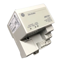
Setting the Switches
 Loading...
