3–6
Communicating with FLEX I/O Modules
Publication
17946.5.3 - May 1996
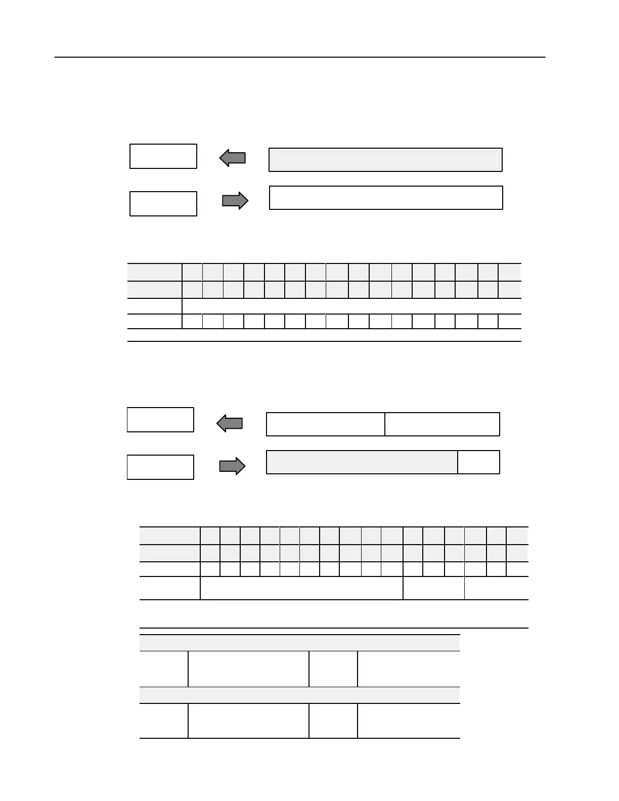
16point Discrete Output Module Image Table Mapping -
1794OB16
Module
Image
Outputs
Input Image
Output Image
Word n
Word n
Remote I/O Image
Example
Address
I:011
O:011
Not used
Memory Map of 16-Point Discrete Output Module Image Table –
1794-OB16
Decimal Bits 15 14 13 12 11 10 09 08 07 06 05 04 03 02 01 00
(Octal Bits) 17 16 15 14 13 12 11 10 07 06 05 04 03 02 01 00
Input word
Not
used
Output word
O15 O14 O13 O12 O11 O10 O9 O8 O7 O6 O5 O4 O3 O2 O1 O0
Where O
= Output value
8point Discrete Input Module Image Table Mapping - 1794IB8S
Module
Image
Inputs
Delay
Time
Status
Input Image
Output Image
Word n
Word n
Remote I/O Image
Example
Address
I:012
O:012
Not used
Memory Map of 8-Point Discrete Input Module Image Table
(with Status) – 1794-IB8S
Decimal Bits 15 14 13 12 11 10 09 08 07 06 05 04 03 02 01 00
(Octal Bits) 17 16 15 14 13 12 11 10 07 06 05 04 03 02 01 00
Input
word
D7 D6 D5 D4 D3 D2 D1 D0 S7 S6 S5 S4 S3 S2 S1 S0
Output word
Not used
DT 12-15
(14-17)
DT 00-1
1
(00-13)
Where S
= Status of input
D = Input Data
DT = Input Delay T
ime
Smart
Sensor
(such as AllenBradley Series 9000 Heartbeat Sensors)
Bits
08-15
(10-17)
D
= Diagnostic data -
1 = Fault present (Smart)
0 = Normal (no errors)
Bits
00-07
(00-07)
S = Input data
1 = Sensor on
0 = Sensor of
f
Standard
Sensor
Bits
08-15
(10-17)
D
= Diagnostic data -
1 = Diagnostics not disabled
0 = Normal (Disabled)
Bits
00-07
(00-07)
S = Input data
1 = Sensor on
0 = Sensor of
f

 Loading...


