3–12
Communicating with FLEX I/O Modules
Publication
17946.5.3 - May 1996
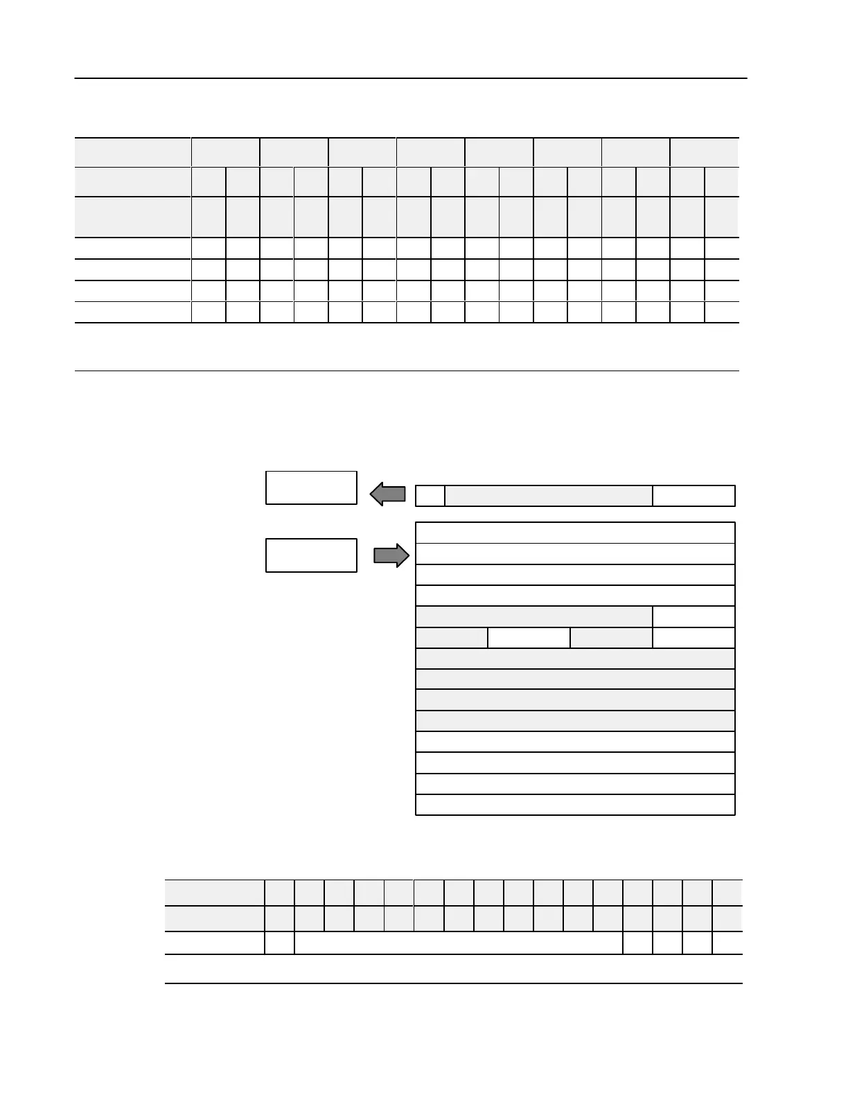
Range Selection Bits for the 1794-IE8/B Analog Input Module
Channel No. Channel 0 Channel 1 Channel 2 Channel 3 Channel 4 Channel 5 Channel 6 Channel 7
F0 C0 F1 C1 F2 C2 F3 C3 F4 C4 F5 C5 F6 C6 F7 C7
Decimal Bits
(Octal Bits)
00
08
(10)
01
09
(11)
02
10
(12)
03
11
(13)
04
12
(14)
05
13
(15)
06
14
(16)
07
15
(17)
0-10V dc/0-20mA 1 0 1 0 1 0 1 0 1 0 1 0 1 0 1 0
4-20mA 0 1 0 1 0 1 0 1 0 1 0 1 0 1 0 1
10 to +10V dc 1 1 1 1 1 1 1 1 1 1 1 1 1 1 1 1
Off
1
0 0 0 0 0 0 0 0 0 0 0 0 0 0 0 0
C
= Configure select bit
F = Full range bit
1
When configured to of
f, individual channels will return 0000H on Series B modules, and 4 to 20mA on Series A modules.
4 Output Analog Module (Cat. No. 1794OE4 Series B)
Module
Image
I/O Image
Analog Data Channel 0
Analog Data Channel 1
Analog Data Channel 2
Analog Data Channel 3
Not used
Not used Not used
Not used
Not used
Not used
Not used
Not used
Diagnostics
Config. Select
Full Range
Input Size
Output Size
0 or 1 Word
1 or 14 Words
Read
Write
MC
PU
Safe State Value - Channel 0
Safe State Value - Channel 1
Safe State Value - Channel 2
Safe State Value - Channel 3
Analog Output Module (1794-OE4) Read
Word/Dec. Bit 15 14 13 12 11 10 09 08 07 06 05 04 03 02 01 00
Word/Octal Bit 17 16 15 14 13 12 11 10 07 06 05 04 03 02 01 00
Read Word 0 PU Not used - set to 0 W3 W2 W1 W0
Where: W
= Diagnostic bits for current output - wire broken or load resistance high. (420mA mode only. Not used on voltage outputs.)
PU = Power up bit (Included in series B modules; this bit is 0 in series A modules.)

 Loading...


