Chapter
3
Publication
17946.5.3
Communicating with
FLEX I/O Modules
In this chapter, we tell you about:
• addressing your I/O
• what combination of I/O modules and I/O chassis you can use
• I/O image table usage
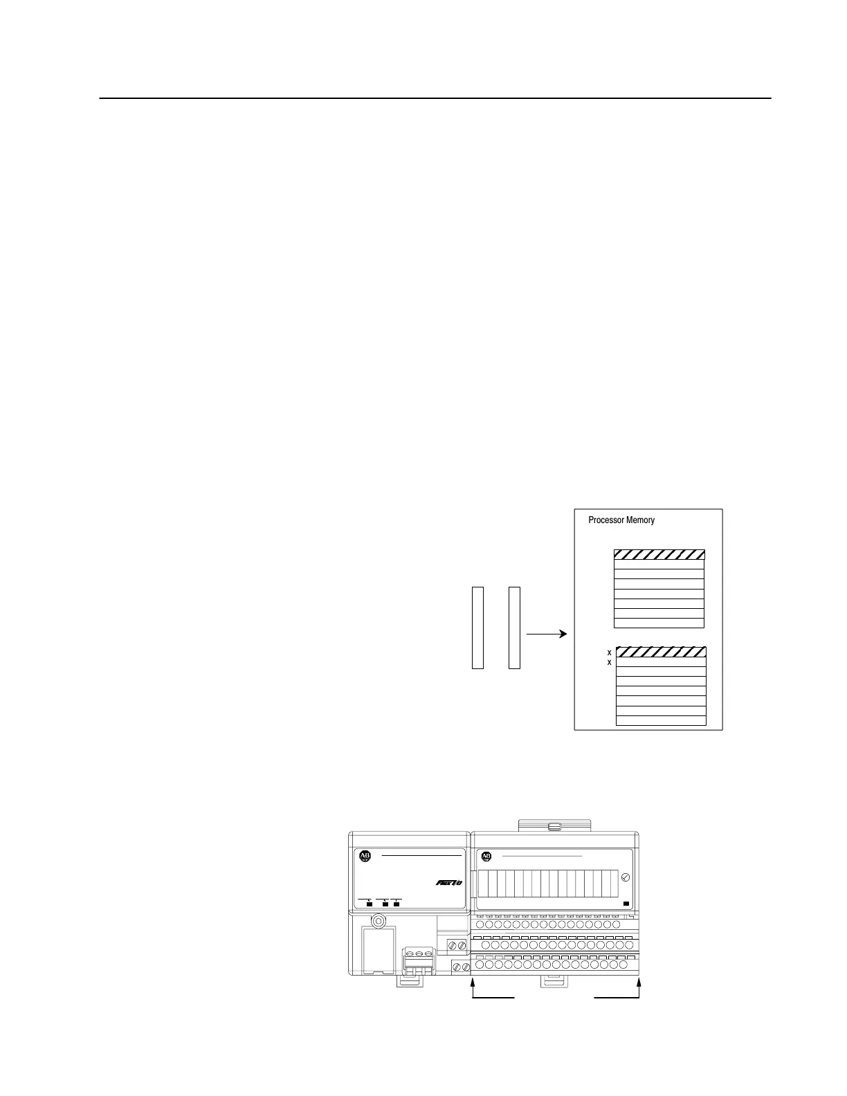
Programmable controllers that use the remote I/O adapter module
address their I/O in I/O groups.
For each FLEX I/O chassis in your system, the remote I/O adapter
must define how many I/O groups exist (1 word each in the input
image table and output image table). With FLEX I/O, each module
equals one I/O group – 1 word of input image and 1 word of output
image.
1 I/O group = 1 input image word and 1
output image word = 16 input bits and
16 output bits.
x
x
x
x
x
x
x
x
Output
Image T
able
W
ord #
Input Image T
able
W
ord #
16
bits input
16 bits output
Processor
Memory
x
x
x
x
x
x
x
x
Rack #
Connections to I/O groups are made to I/O terminals (as shown
below). An I/O group is an addressing unit that can contain up to 16
input terminals and 16 output terminals.
20126
24VDC
POWER SUPPLY
RIO ADAPTER
AllenBradley
1794ASB
2
AllenBradley
0 1 2 3 4 5 6 7 8 9 10 11 12 13 14 15
One I/O Group
Chapter Objectives
Hardware Addressing

 Loading...


