3–2
Communicating with FLEX I/O Modules
Publication
17946.5.3 - May 1996
I/O racks are made up of I/O groups. An I/O rack is an addressing
unit that can contain up to eight I/O groups.
You can use as many as 8 modules per adapter. This provides a
maximum of 128 discrete I/O or 64 analog inputs, or 32 analog
output channels.
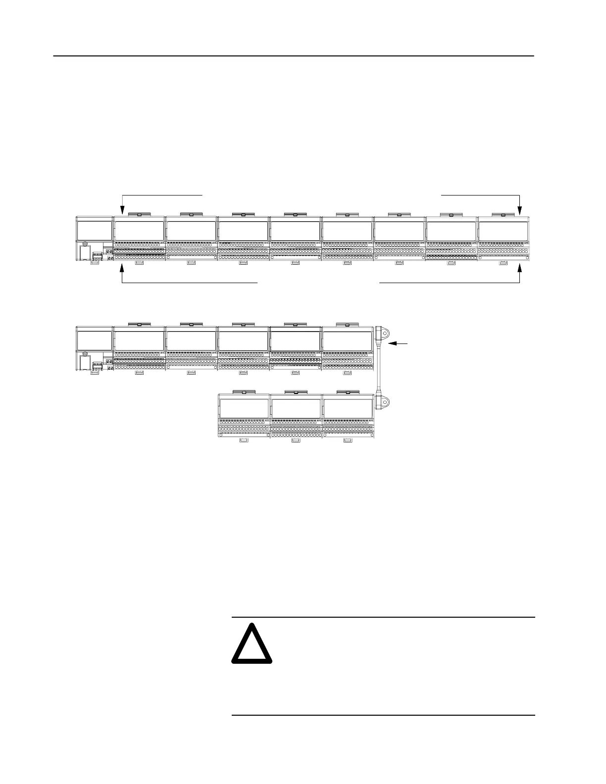
Figure 1
An I/O Rack Up to Eight I/O Groups
Any combination of discrete digital or analog modules.
Eight terminal bases (maximum)
Adapter
20128
Each terminal base represents 1 I/O group
Group 0 Group 1 Group 2 Group 3 Group 4 Group 5 Group 6 Group 7
Group 0 Group 1 Group 2 Group 3 Group 4
Group 7 Group 6 Group 5
Optional 1794CE1 or CE3
Extender Cable
When using the optional extender cable, modules groups are numbered sequentially along the length of the string.
Do not use the extender cable to connect the adapter to the first module
Important: Only 1 extender cable is
allowed per system.
After the remote I/O adapter has identified the modules present in its
system, it creates a “rack image” so data transfer can take place using
the remote I/O protocol.
Building a rack image consists of:
• mapping each module to one I/O group (16 bits of input and 16
bits of output)
• determining rack size – all empty terminal bases are counted
unless they occur at the end of the rack
• automatically sizing the rack image
!
ATTENTION: Do not use the auto-config feature of
6200 software when using a PLC-3 processor with
1775-S4A or 1775-S4B scanner modules. If you do an
auto-config for a scanner channel containing 1 or more
1794-ASB adapters with that configuration, the
adapters may not show up in the scan list for that
scanner channel. Manually insert these adapters into
the scan list for the scanner.
Determining Rack Size

 Loading...


