2–5
Installing Your Remote I/O Adapter Module
Publication
17946.5.3 - May 1996
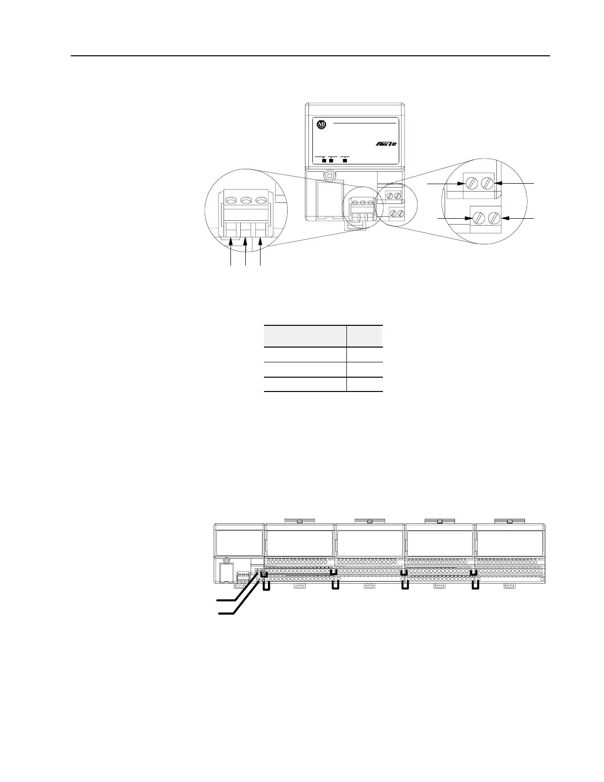
Connect external wiring to the remote I/O adapter as shown below.
1
SH
2
BC
D
A
20131
24V
COM
AllenBradley
24 VDC
POWER SUPPLY
RIO ADAPTER
1794-ASB
ADAPTER
ACTIVE FAULT
LOCAL
FAULT
1. Connect the remote I/O cable to the removable plug-in remote
I/O connector.
Connect To
Blue Wire - RIO 1
Shield Wire - RIO SH
Clear Wire - RIO 2
2. Connect +24V dc input to the left side of the lower connector
terminal A.
3. Connect 24V common to the left side of the upper connector
terminal B.
4. Connections C and D are used to pass 24V dc power and
common to the next module in the series (if required).
For example:
Wiring
when total current draw is less than 10A
Daisychaining
24V dc
Note:
Refer to the individual instructions for each module for actual wiring information.
Note:
All modules must be either analog or discrete. Do not mix analog
and discrete modules when using the daisychain wiring scheme.
Wiring

 Loading...


