3–18
Communicating with FLEX I/O Modules
Publication
17946.5.3 - May 1996
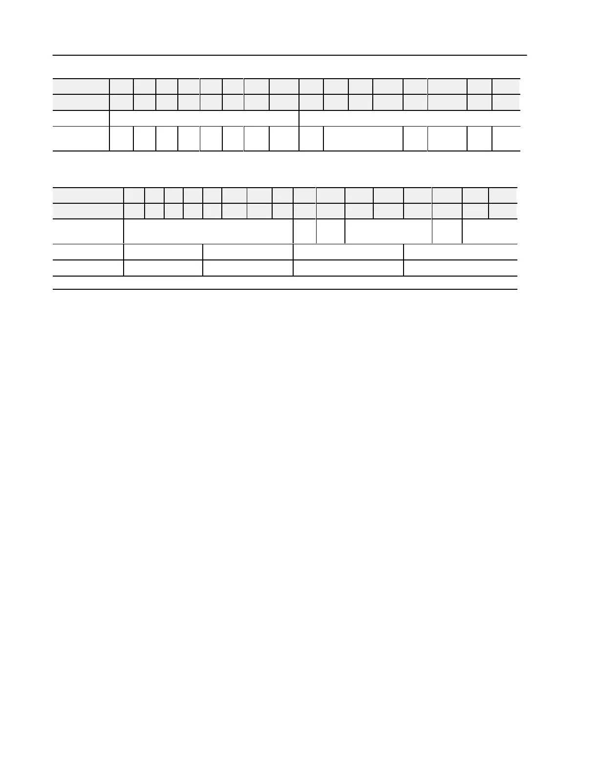
00010203040506070809101112131415Decimal Bit
00010203040506071011121314151617Octal Bit
9 Overrange Bits Underrange Bits
10 0 0 0 0 0
Bad
Cal
Cal
Done
Cal
Range
0 Diagnostic Status
Pwr
Up
Bad
Structure
CJC
over
CJC
Under
Thermocouple/mV Input Module (1794-IT8) Write
Dec. Bit 15 14 13 12 11 10 09 08 07 06 05 04 03 02 01 00
Octal Bit 17 16 15 14 13 12 11 10 07 06 05 04 03 02 01 00
Write Word 0 8Bit Calibration Mask
Cal
Clk
Cal hi
Cal lo
Filter Cutoff FDF Data Type
1 Thermocouple 3 Type Thermocouple 2 Type Thermocouple 1 Type Thermocouple 0 Type
2 Thermocouple 7 Type Thermocouple 6 Type Thermocouple 5 Type Thermocouple 4 Type
Where: FDF
= fixed digital filter bit
Most reset commands are issued by the processor when it is placed
in the PROG mode. However, the processor automatically issues a
special command to any rack declared faulted regardless of the
processor mode.
When this special command is received by the faulted remote I/O
adapter, and processor restart lockout (PRL) has not been selected,
the adapter will:
• continue to read output image data from the link, and queue block
transfers if MCBs are detected
• reset all bits in the output words of discrete modules
• reset all bits in the write words of analog modules up to but not
including the write words of the safe state values
• assigns safe state values to outputs of analog modules
• issue a reply command
If processor restart lockout (PRL) has been selected, the adapter does
not update data, does not issue a reply command, and does not clear
the fault.
In this chapter, you learned how to address your I/O, how to
determine rack size, and how the modules are mapped
Operating Modes
Chapter Summary

 Loading...


