Rockwell Automation Publication 2198-UM002G-EN-P - February 2019 89
Mount the Kinetix 5700 Drive System Chapter 3
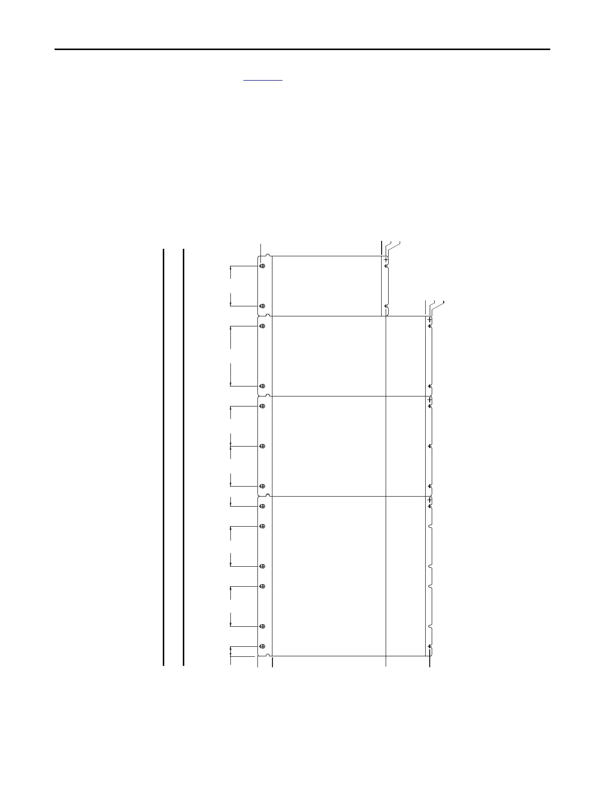
Use Figure 53 to calculate the left-to-right hole pattern for Kinetix 5700 drive
system configurations that include the 2198-RPxxx regenerative bus supply.
Mounting holes for the Kinetix 5700 regenerative bus supply modules are
based on 55 mm spacing, however, only the holes specified for each module are
required.
Figure 53 - Regenerative Bus Supply Mounting Hole Patterns
176 (6.93)
Lower Mounting Hole
345 (13.58)
Lower Mounting Hole
420 (16.54)
Lower Mounting Hole
27.5
55.0
8.0
55.0
110 55.0
110 110 165
110
110
32.00
0.0 Upper
Mounting Holes
332 Module Height
345 Ground Stud
350
452 Module Height
465 Ground Stud
470
345 Lower
Mounting Hole
465 Lower
Mounting Hole
2198-RP312
2198-RP263
Regenerative Bus Supply
(440 mm module width)
2198-RP200
Regenerative Bus Supply
(275 mm module width)
2198-S263-ERSx
2198-S312-ERSx
Single-axis Inverter
(220 mm module width)
2198-RP088
Regenerative
Bus Supply
(165 mm
module width)
IMPORTANT
Hole spacing is measured in millimeters and not converted to inches to avoid errors due to rounding.
 Loading...


