Disassembly / Assembly Diagrams D-7
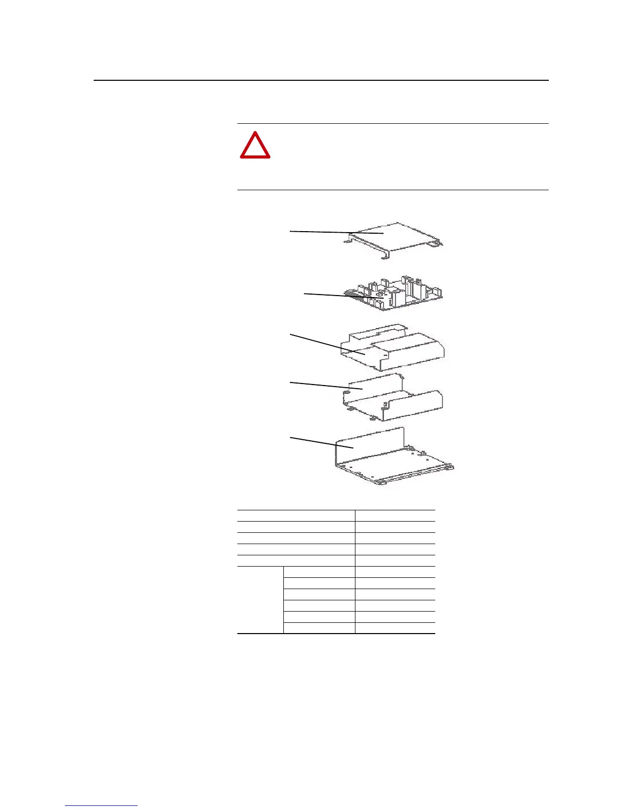
Figure D.6 ASIC Assembly
Table D.F ASIC Assembly Part Numbers
!
ATTENTION: The sheet metal cover and mounting screws on
the ASIC Board located on the power structure are energized at
(-) DC bus potential high voltage. Risk of electrical shock,
injury, or death exists if someone comes into contact with the
assembly.
Part Name Spare Part No.
ASIC Assembly Bracket NA
ASIC Assembly Bracket NA
ASIC Assembly Bracket NA
ASIC Assembly Cover NA
ASIC Board
400/480V, 590A SK-H1ASICBD-D590
400/480V, 650A SK-H1ASICBD-D650
400/480V, 730A SK-H1ASICBD-D730
600/690V, 460A SK-H1ASICBD-E460
600/690V, 502A SK-H1ASICBD-E502
600/690V, 590A SK-H1ASICBD-E590
ASIC Assembly
Cover
ASIC Board
ASIC Assembly
Bracket
ASIC Assembly
Bracket
ASIC Assembly
Bracket

 Loading...


