Component Test Procedures 2-5
1. Remove power from the drive. Refer to Removing Power from the
Drive on page 3-3.
2. Disconnect the motor leads from the drive.
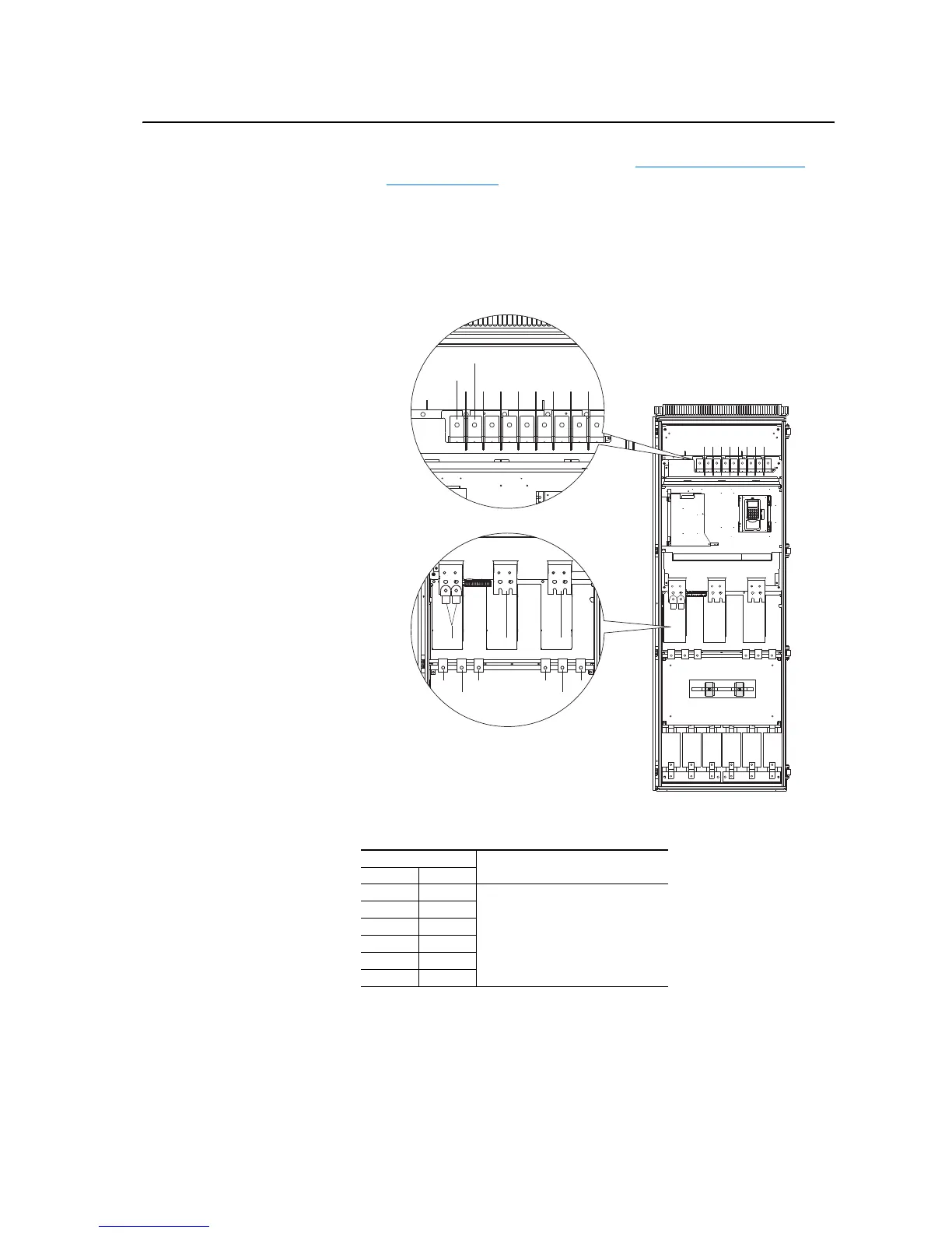
3. On ac input drives, conduct forward and reverse biased diode tests on
the Rectifying module(s).
Figure 2.1 Measurement Points for Forward and Reverse Diode Tests
Table 2.A Forward Biased Diode Tests on Rectifying Module(s)
Meter Leads
Nominal meter reading+-
L1 DC+
Value should gradually rise to about
0.5V
L2 DC+
L3 DC+
DC- L1
DC- L2
DC- L3
2L1
2L2
2L31L1
1L2
1L3
U/T1 V/T2 W/T3
DC-
DC+
Note: 600V ac input, 460A and 502A frame 11
drives only have one Rectifying module.

 Loading...


