2-6 Component Test Procedures
If the drive fails any of these measurements, replace all Rectifying modules.
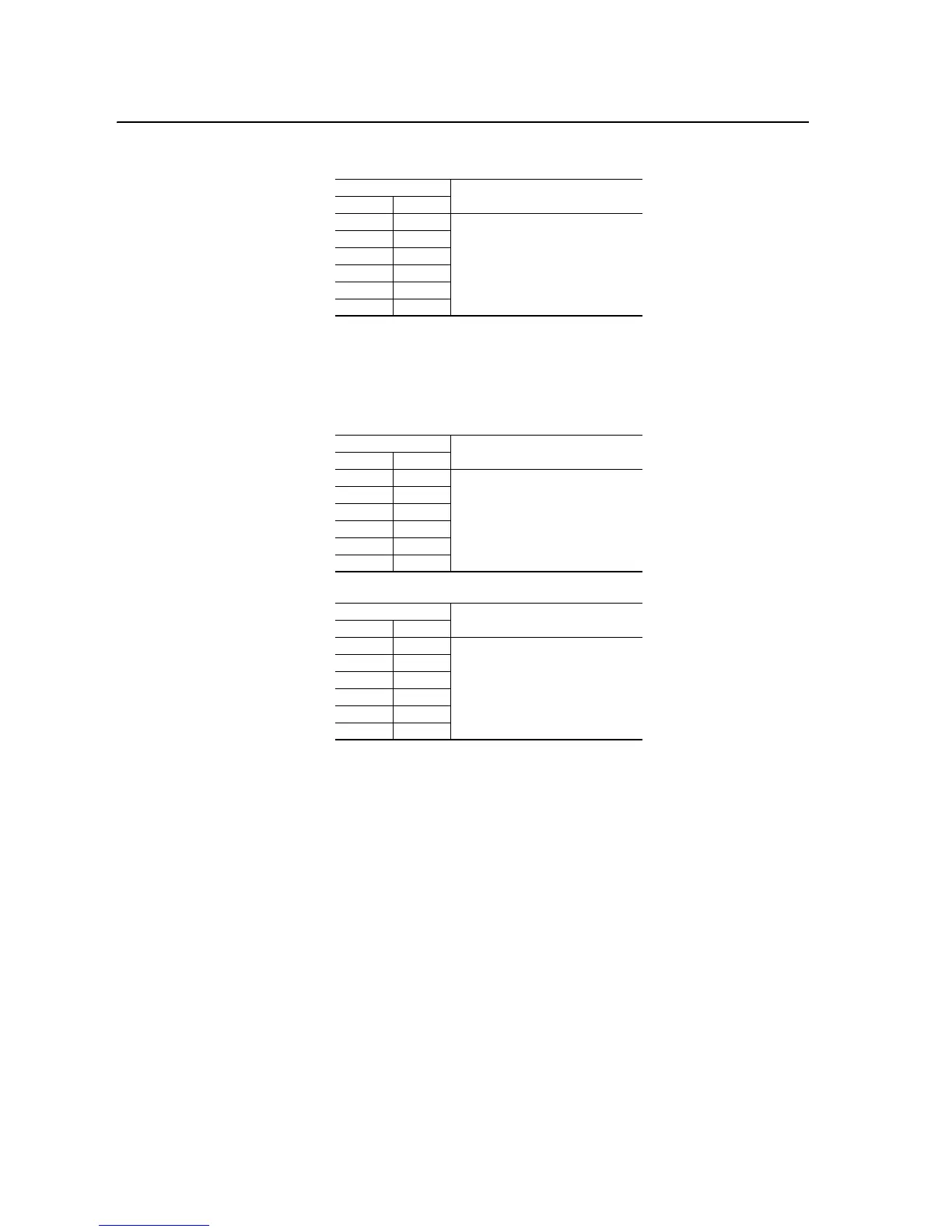
4. Conduct forward and reverse biased diode tests on the Output Power
modules.
If the drive fails any of these measurements, replace all three Output
Power modules.
Table 2.B Reverse Biased Diode Tests on Rectifying Module(s)
Meter Leads
Nominal meter reading+-
L1 DC-
Meter should display “.0L” (zero load)
L2 DC-
L3 DC-
DC+ L1
DC+ L2
DC+ L3
Table 2.C Forward Biased Diode Tests on Output Power Modules
Meter Leads
Nominal meter reading+-
DC- T1
Meter should display “.0L” (zero load)
DC- T2
DC- T3
T1 DC+
T2 DC+
T3 DC+
Table 2.D Reverse Biased Diode Tests on Output Power Modules
Meter Leads
Nominal meter reading+-
T1 DC-
Value should gradually rise to about
0.5V
T2 DC-
T3 DC-
DC+ T1
DC+ T2
DC+ T3

 Loading...


