Motion Event Instructions
Rockwell Automation Publication MOTION-RM002H-EN-P-February 2018 295
Mode Compensation
Depending on the selected mode, the compensated output bit is set according to
the following table.
Mode Behavior When
Normal
The output bit is set
the output of the latch and unlatch operation
becomes active.
The output bit is reset
the output of the latch and unlatch operation
becomes inactive.
Inverted
The output bit is set
the output of the latch and unlatch operation
becomes inactive.
The output bit is reset
the output of the latch and unlatch operation
becomes active.
Pulsed
The output bit is pulsed
when the output of the latch and unlatch operation is
active. The on-duty state of the pulse corresponds to
the active state of the output bit.
The output bit is reset
the output of the latch and unlatch operation
becomes inactive.
Inverted and Pulsed
The output bit is pulsed
the output of the latch and unlatch operation is
active. The on-duty state of the pulse corresponds to
the inactive state of the output bit.
The output bit is set
the output of the latch and unlatch operation
becomes inactive.
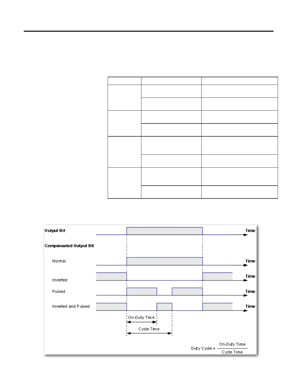
The following diagram shows the effect of the mode, cycle time, and duty cycle on
an output bit.
 Loading...


