Page 20
Allied Telesis AT-8000SSwitch
Switch Installation Guide
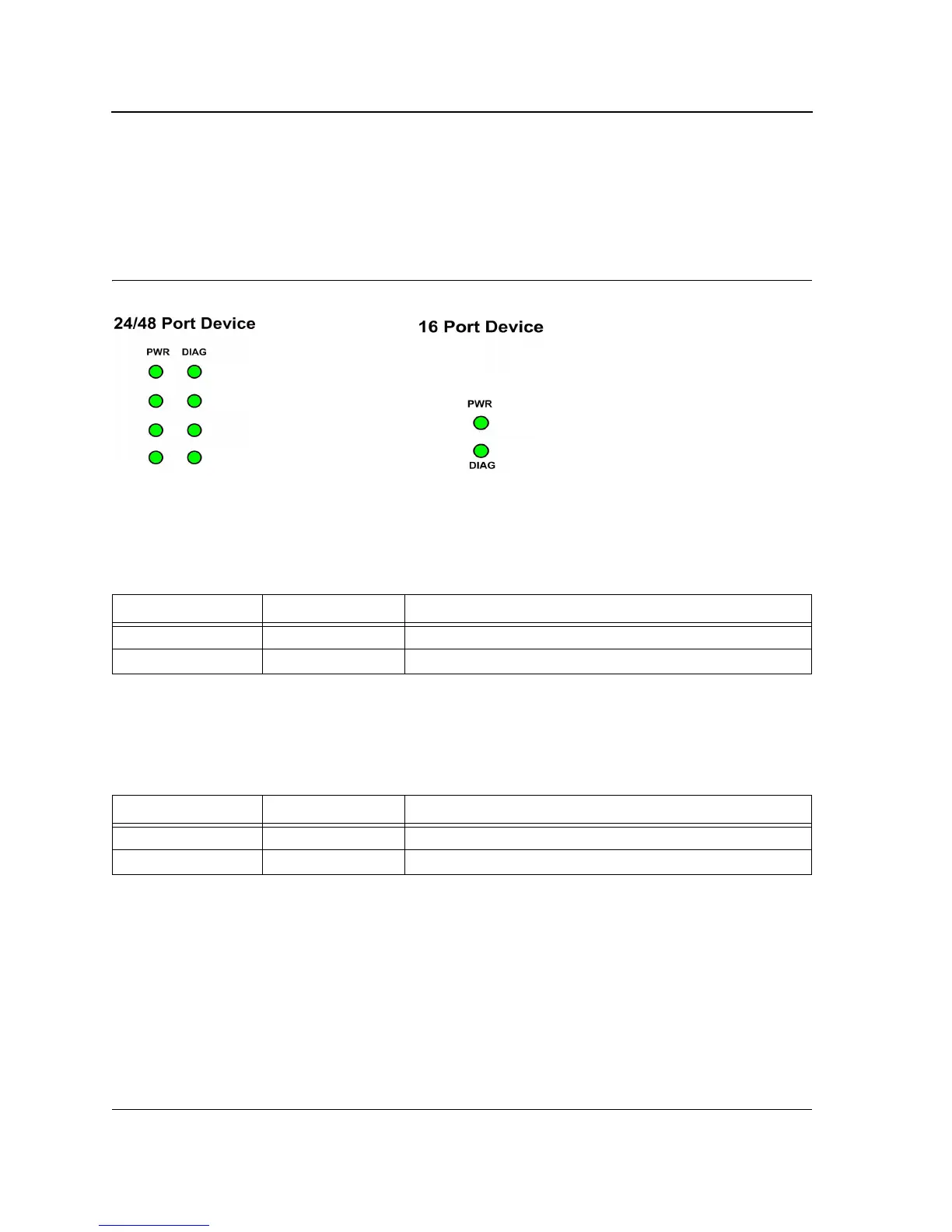
24/48 Port Device System LEDs
There are two system LEDs, the Power and Diagnostics LEDs.
The following figure illustrates the Power and Diagnostics LEDs.
Figure 16: SFP Port LEDs
Power LED
The PWR LED on the front panel of the device indicates the power supply status.
The power supply port LED indications are described in the following table:
Diagnostic LED
The DIAG LED on the front panel of the device indicates the diagnostics results.
The diagnostics LED indications are described in the following table:
Table 6: Power Supply LED Indications
LED Description LED Indication Description
Power Off The system is not powered up (power off).
Green Main power is functional (normal operation).
Table 7: Diagnostics LED Indications
LED Description LED Indication Description
DIAG Flashing green System diagnostics has failed.
Green System diagnostics successfully completed.

 Loading...