Chapter 2 Installation and Wiring
X1~X6
R
COM
+24V
24V
5V
PLC
+
-
K
+
-
DC
R
+24V
5V
+
-
K
+
-
DC
24V1
PLC1
X7~X10
COM1
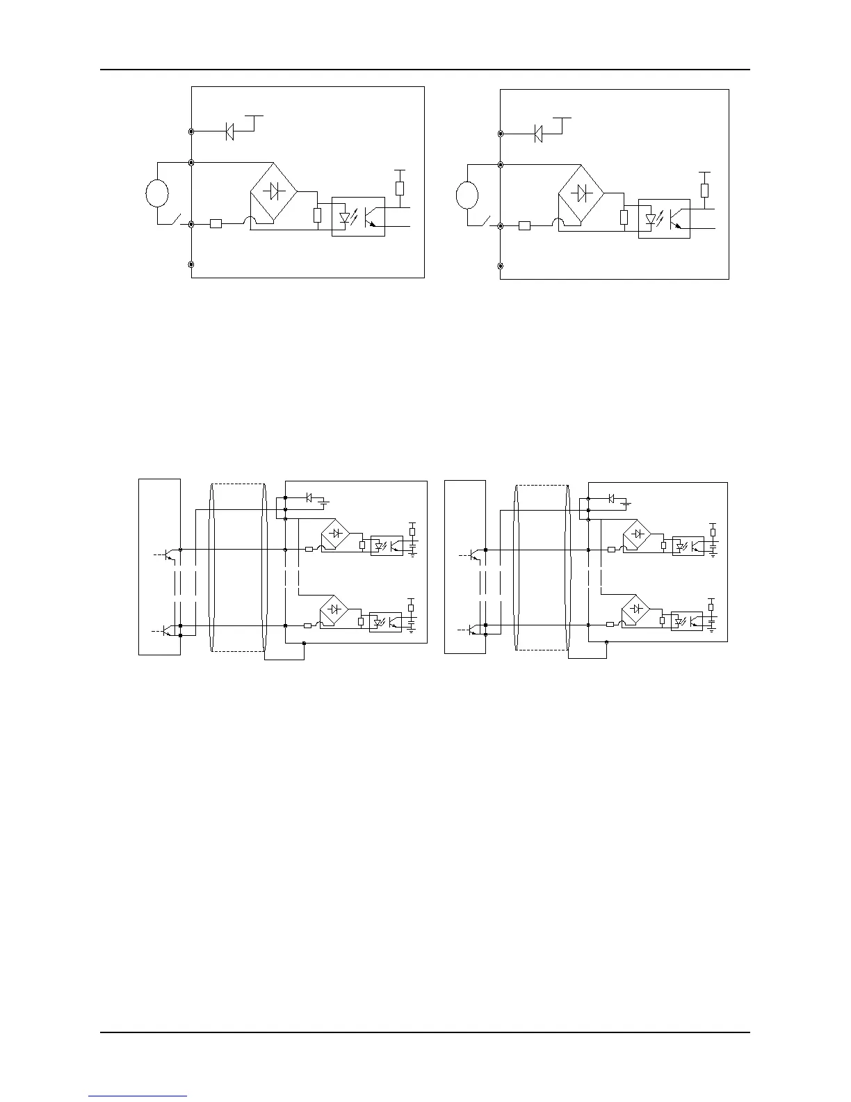
Fig. 2-19 Connection diagram while using an external
power supply (control board)
NOTE: Remove the short jumper JP1 connecting
internal PLC and 24V
Fig. 2-20 Connection diagram while using outside
power supply (extension board)
NOTE: Remove the short jumper JP1 connecting
internal PLC1 and 24V1
Source (drain electrode) mode
1) Use internal +24 V power of the inverter. External controller is the connection mode of NPN type common
emitter output, which is shown in Fig. 2-21 (control board) and Fig. 2-22 (extension board).
X1
PE
24V DC
24V
5V
PLC
+
-
外部控制器
COM
5V
+
-
X6
COM
1
6
屏蔽线近端接地
+
-
X7
PE
24V DC
24V1
5V
PLC1
+
-
外部控制器
COM1
5V
+
-
X10
COM
7
10
屏蔽线近端接地
+
-
Fig. 2-21 Connection diagram while using source of
internal + 24V power supply (control board)
Fig. 2-22 Connection diagram while using source of
internal + 24V power supply (extension board)
2) Use internal +24 V power of the inverter. External controller is the connection mode of PNP type common
emitter output, which are shown in Fig. 2- 23 (control board) and Fig. 2-24 (extension board).
Near-end of shield
line is grounded
Near-end of shield
line is grounded