Chapter 2 Installation and Wiring
X1
PE
24V DC
24V
5V
PLC
+
-
外部控制器
COM
5V
+
-
X6
1
6
屏蔽线近端接地
+
-
X7
PE
24V DC
5V
+
-
外部控制器
5V
+
-
X10
7
10
屏蔽线近端接地
+
-
24V1
PLC1
COM1
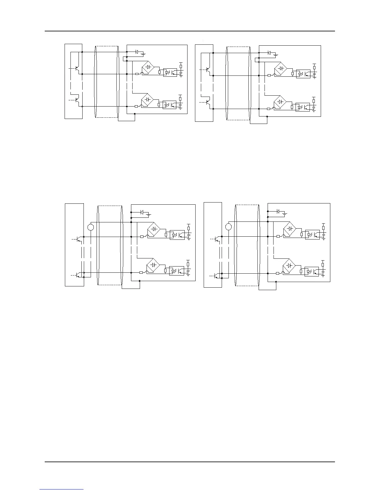
Fig. 2-23 Connection diagram while using drain
electrode of internal + 24V power supply (control
board)
NOTE: Remove the short jumper JP1 connecting PLC and 24V,
and connect PLC to COM
Fig. 2-24 Connection diagram while using drain
electrode of internal + 24V power supply (extension
board)
NOTE: Remove the short jumper JP1 connecting PLC1 and
24V1, and connect PLC1 to COM1
3) Use connection mode of source of an external power, as shown in Fig. 2-25 (control board) and Fig. 2-26
(extension board).
X1
PE
24V DC
24V
5V
PLC
+
-
外部控制器
COM
5V
+
-
X6
COM
1
6
屏蔽线近端接地
+
-
+
-
9~30V
X7
PE
24V DC
5V
+
-
外部控制器
5V
+
-
X10
COM
7
10
屏蔽线近端接地
+
-
+
-
9~30V
24V1
PLC1
COM1
Fig. 2-25 Connection diagram while using source of
external power (control board)
NOTE: Remove the short jumper JP1 connecting internal PLC
and 24V
Fig. 2- 26 Connection diagram while using source of
external power (extension board)
NOTE: Remove the short jumper JP1 connecting internal PLC1
and 24V1
4) Use connection mode of drain electrode of an external power as shown in Fig. 2-27 (control board) and Fig. 2-28
(extension board).
Near-end of shield
line is grounded
Near-end of shield
line is grounded
Near-end of shield
line is grounded
Near-end of shield
line is grounded