Chapter 2 Installation and Wiring
X1
PE
24V DC
24V
5V
PLC
+
-
外部控制器
COM
5V
+
-
X6
1
6
屏蔽线近端接地
+
-
+
-
9~30V
X7
PE
24V DC
5V
+
-
外部控制器
5V
+
-
X10
7
10
屏蔽线近端接地
+
-
+
-
9~30V
24V1
PLC1
COM1
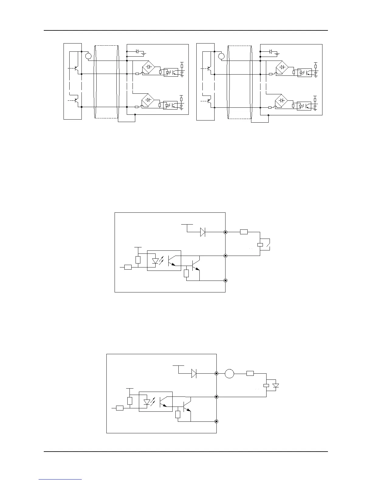
Fig. 2-27 Connection diagram while using drain
electrode of an external power (control board)
NOTE: Remove the short jumper JP1 connecting internal PLC
and 24V
Fig. 2-28 Connection diagram while using drain
electrode of an external power (extension board)
NOTE: Remove the short jumper JP1 connecting internal PLC1
and 24V1
● Wire Multi-function Output Terminals
1) Multi-function output terminals D0 as switching output can use the internal 24V power supply of inverter and the
wiring method is shown in Figure 2-29.
Fig. 2-29 On-off output connection mode 1 of multi-function output terminals
2) Multi-function output terminals DO as switching output can also use the external, 9~30V, power supply and
the wiring method is shown in Figure 2-30
COM
DO
24V
+24V
5V
继电器
DC 9~30V
+
-
R
Fig. 2-30 On-off output connection mode 2 of multi-function output terminals
Near-end of shield
line is grounded
Near-end of shield
line is grounded