Chapter 2 Installation and Wiring
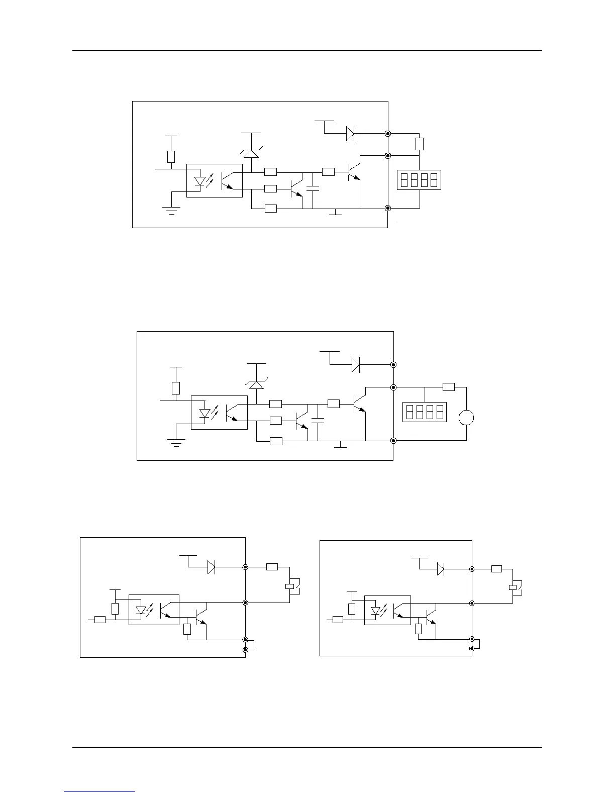
3) Multi-function output terminals / Pulse output terminal DO as pulse output can use the internal 24V power supply
and the wiring is shown in Figure 2-31.
Fig. 2-31 Digital pulse output connection mode 1 of multi-function output terminals
4) Multi-function output terminals / Pulse output terminal DO as Pulse output can also use the external, 9~30V,
power supply and the wiring is shown in Figure 2-32
5V
+24V
24V
DO
COM
+24V
R
数字频率计
DC
9~30V
+
-
Fig. 2-32 Digital pulse output connection mode 2 of multi-function output terminals
5) Multi-function output terminals Y1, Y2, Y3 can use 24V internal power of the inverter with the connection modes
shown in Fig. 2-33 (control board) and Fig. 2-34 (extension board).
继电器
COM1
CME1
Y2 Y3
24V1
+24V
+5V
Fig. 2-33 Wiring diagram of multi-function output
terminals (control board)
Fig. 2-34 Wiring diagram of multi-function output
terminals ( extension board)
Digital frequency
statistics
Digital frequency
statistics