Chapter 2 Installation and Wiring
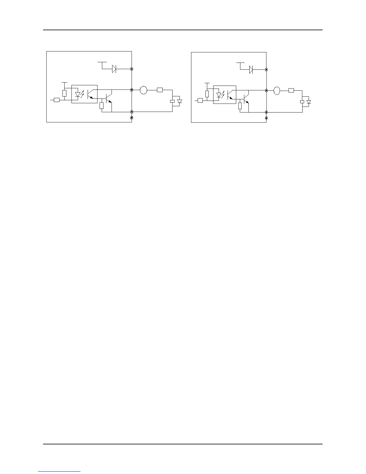
6) Multi-function output terminals Y1, Y2, Y3 also can use external power (9~30V) with the connection modes as
shown in Fig. 2-35(control board) and Fig. 2-36(extension board).
+5V
+24V
24V
Y1
CME
COM
继电器
DC 9~30V
+
-
+5V
+24V
24V1
Y2 Y3
CME1
COM1
继电器
DC 9~30V
+
-
Fig. 2-35 Wiring diagram of multi-function output
terminals (control board)
Fig. 2-36 Wiring diagram of multi-function output
terminals (extension board)
● Wiring of relay output terminals TA, TB, TC and BRA, BRB, BRC (exclusive for 35R5GB and above
models)
If the drive inductive loads (e.g. electromagnetic relays, contactors) should be equipped with surge voltage
absorption circuit, such as the RC absorption circuit, piezoresistor or flywheel diode (pay attention to the diode
polarity when used for DC electromagnetic circuit), etc. Components of absorption circuit should be installed
close to both ends of coil of relay or contactor.
1. Don’t short circuit terminals 24V and COM, otherwise the control board may be damaged.
2. Please use multi-core shielded cable or multi-stranded cable (above 1 mm) to connect the control terminals.
3. When using a shielded cable, the shielded lay’s end that is nearer to the inverter should be connected to PE.
4. The control cables should be as far away(at least 30 cm) from the main circuit and high-voltage cables as
possible (including power supply cables, motor cables, relay cables and cables of contactor). The cables should
be vertical to each other to reduce the disturbance to minimum.
● Wiring of serial communication interface
The series of inverters provides users with RS485 serial communication interface, and can compose master-slave
control system. The host machine can be a personal computer or PLC controller (called upper computer for short),
and the slave-based machine is this series of inverter. The upper computer can be used for real-time monitoring,
remote control and other operations to inverters in network.
Fig. 2-37 Illustration of wiring between the upper computer and the inverter interface: