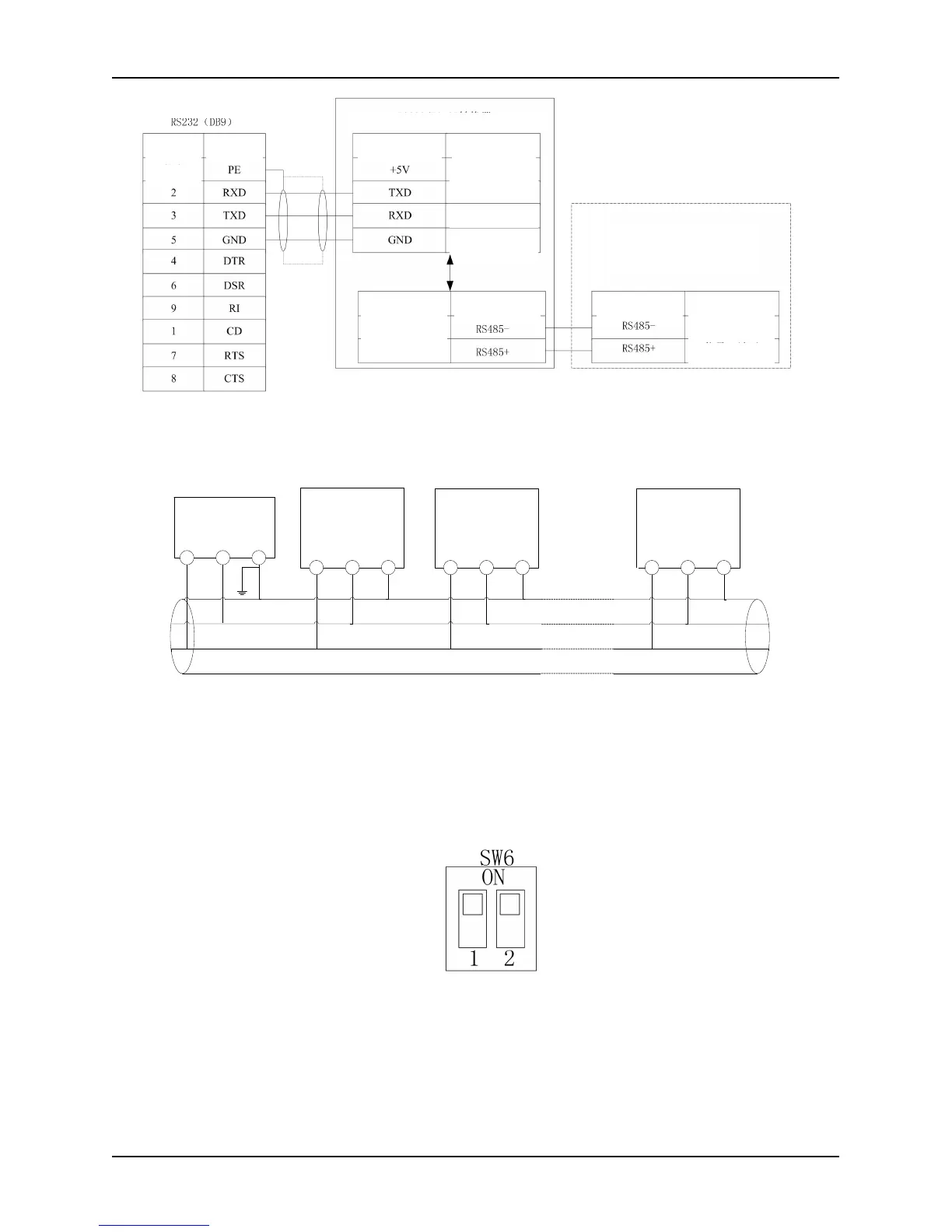
Fig. 2-37 Wiring diagram between the upper computer and the inverter interface
When multiple inverters are connected in one RS485 system, the communication suffers more interference,
and a maximum of 31 inverters can be connected through RS485 serial bus. Wiring is very important.
Communication bus must be shielded twisted pair wiring. The following connection method is recommended:
Fig. 2-38 Recommended wiring diagrams (inverters and motors are all well grounded) when PLC is in multi
computer communication with inverters
When a PC is used as the host machine, a RS232/RS485 bus adapter should be added between the host machine and
the bus; when a PLC controller is used as the host machine, connect the dotted terminals, namely RS485 terminal of
slave-based machine and RS485 terminal of the host machine.
When multiple 35R5GB and above inverters compose RS485 bus communication, the matched resistance toggle
switch SW6 on the control board of this series of inverters at the farthest ends of the bus should be turned to ON
position, as shown in Fig. 2-39.
Fig. 2-39 Schematic illustration of RS485 matched resistance toggle switch
If using the above wiring still cannot communicate normally, the following measures can be taken:
1) Supply the PLC controller (or the upper machine) separately or isolate its power;
2) When using a RS232/RS485 converter module, separate power supply for the modular converter can be
considered. And modular converter with opto-coupler isolation is recommended to use;
3) Apply a magnetic ring on the communication line, and reduce the carrier frequency of the converter
appropriately if site conditions permit.