19
C048-740-30 R02, Rev. C (01/2020)
4.9 4.9 Distribution Panel InstallationDistribution Panel Installation
Depending on the conguration ordered, the BDFB may have
empty panel positions that are covered with blanking plates. If extra
distribution is needed anytime in the future, these plates can be
easily removed and replaced with breaker panels by following these
instructions.
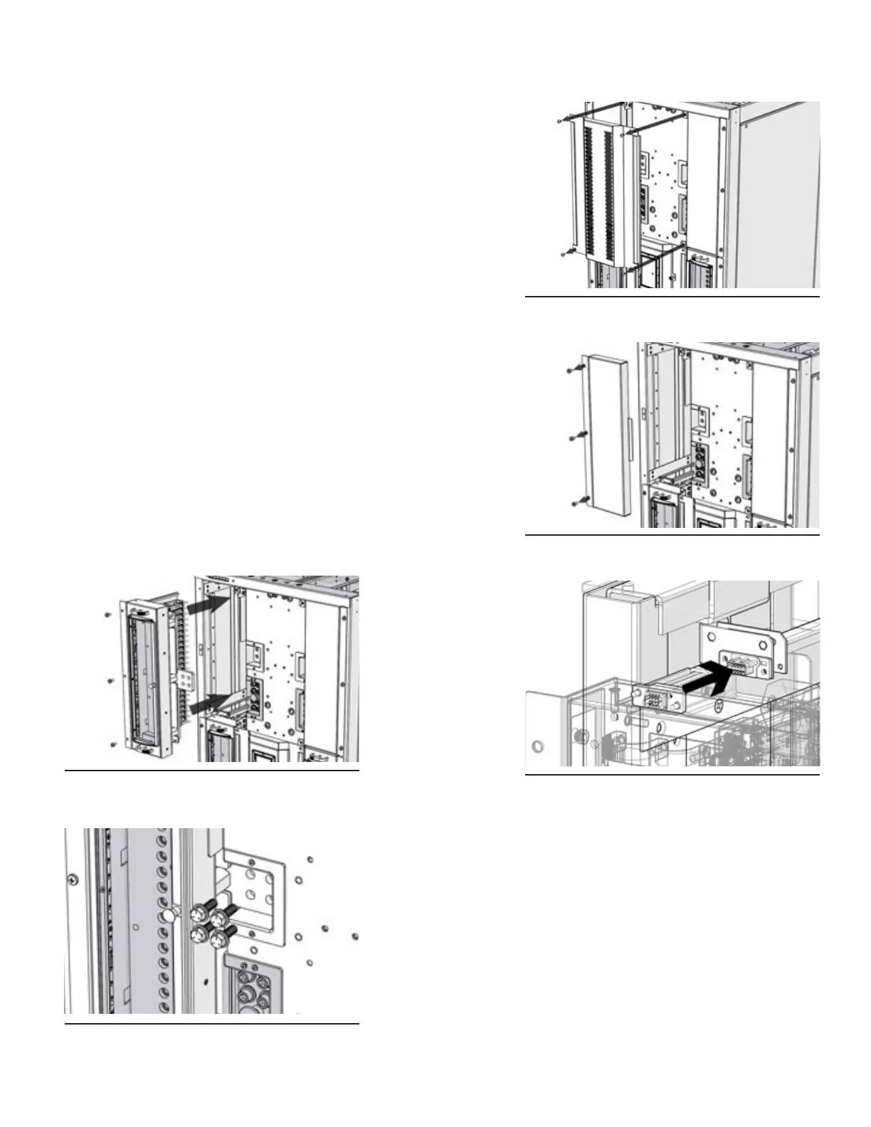
Step 1. Remove the center panel by loosening the four pan head
screws (see Figure 38).
Step 2. Remove the panel blanking plate by removing the three #12-
24 screws from the mounting ear (see Figure 39).
Step 3. Carefully insert the AM breaker panel into the slot (see Figure
40; also applicable for GJ breaker panel). Take caution as to
not damage the panel mount interface connector during panel
insertion (see Figure 41).
Step 4. Secure the panel to the rack assembly by inserting and
tightening down the three #12-24 screws from Step 2 into the
mounting ear.
Step 5. Install and tighten the supplied 3/8 in. hardware to connect
the panel to the hot bus (see Figure 42).
Step 6. Reattach the center blanking panel from Step 1 and tighten
screws.
Figure 38. Center Panel
Figure 39. Panel Blanking Plate
Figure 40. AM Breaker Panel Insertion
Figure 41. Panel Mount Interface
Connector
Figure 42. Panel Connection Hardware