26
C048-740-30 R02, Rev. C (01/2020)
6.4 6.4 BDFB ConguratorBDFB Congurator
The BDFB supervisory controller allows for exible conguration
and reconguration of distribution panels and bus layouts at the
touch of a button. The following illustrations depict a quad-bus BDFB
conguration, however these instructions are applicable for all other
panel/jumper congurations oered.
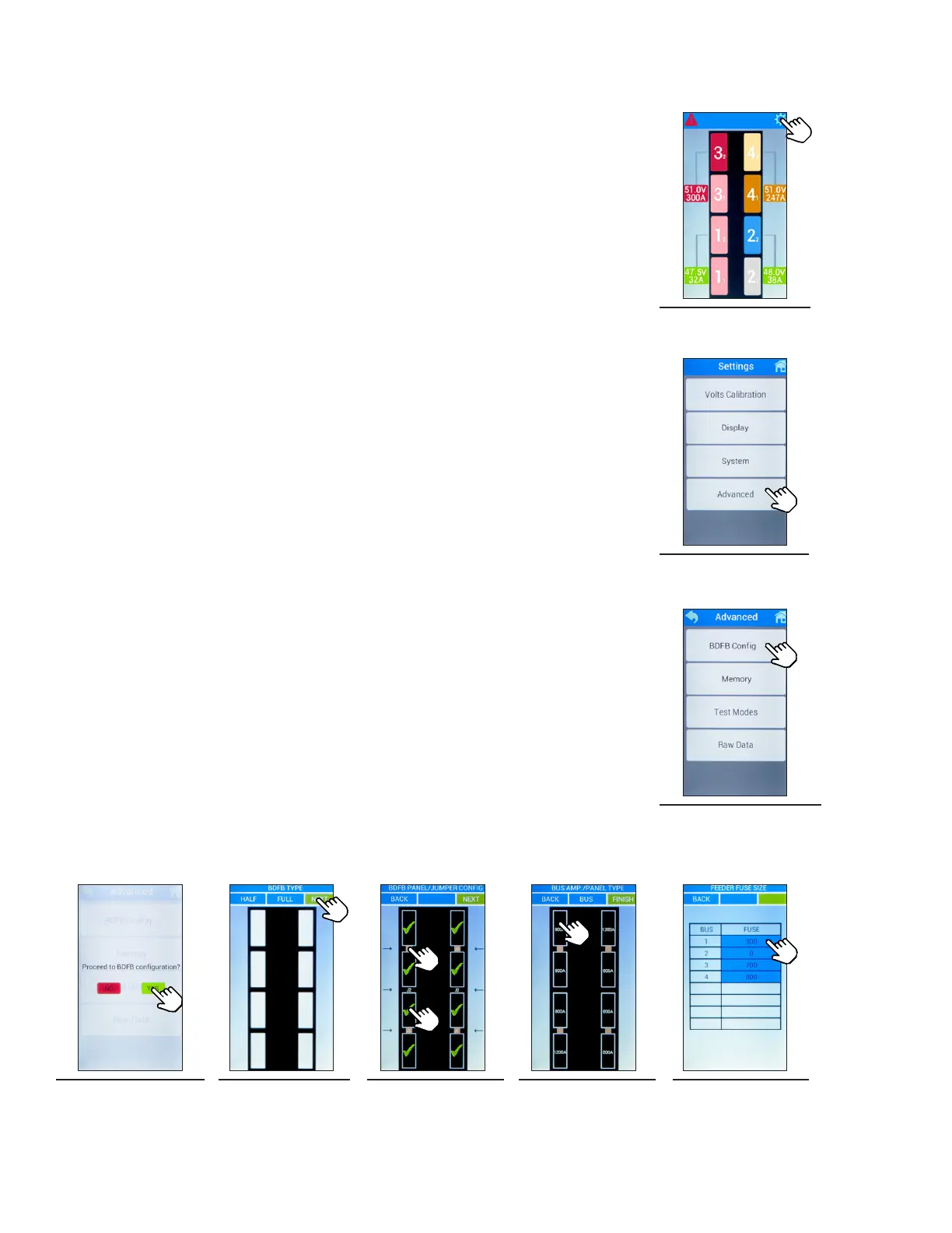
Step 1. Access the settings menu by tapping the gear icon located in
the upper right-hand corner (see Figure 52).
Step 2. Select the Advanced button (see Figure 53).
Step 3. Select the BDFB Cong button (see Figure 54).
Step 4. Select YES to proceed to the BDFB conguration screen (see
Figure 55).
Step 5. Select FULL for BDFB Type and then select NEXT (see
Figure 56).
Step 6. Select the distribution panel icons (rectangular outlines) to
assign panels. A check mark will appear for each selected
panel. Assign bus jumpers (J1/J2/J3) by tapping the area
between the distribution panel icons. The jumper icons will
appear as a bronze color when selected (see Figure 57).
Once the panel/jumper positioning has been chosen, select
NEXT.
Step 7. Tap the distribution panel icons to change ampacity between
800A and 1200A as needed (see Figure 58).
Step 8. Select BUS to access the feeder fuse size menu. Within each
bus, the fuse value can be adjusted by intervals of 50A by
tapping the fuse amperage number until the required
amperage is met (see Figure 59). Select BACK to return to
the BUS AMP./PANEL TYPE menu. The range is between
300 - 1200A. 0 means the fuse is not installed.
Step 9. Select FINISH to complete the BDFB conguration process.
Figure 52. Main
Menu
Figure 53. Settings
Figure 54. Advanced
Figure 55. Proceed
to BDFB
Conguration
Figure 56. BDFB
Type
Figure 57. Panel/
Jumper
Conguration
Figure 58. Panel
Ampacity
Figure 59. Feeder
Fuse Size