22
C048-740-30 R02, Rev. C (01/2020)
6.0 6.0 OperationOperation
The Full-Size BDFB is available with an optional supervisory controller module
to allow for precise monitoring of bus, panel, and breaker alarms.
6.1 6.1 Menu IconsMenu Icons
Navigation within the supervisory controller is performed by tapping the icons
located at the top of the screen.
Table 16. Icon Key
ICON FUNCTION ICON FUNCTION
Settings Breaker Ampacity
Home Load Calibration
Return Mute Volume
Breaker Inventory
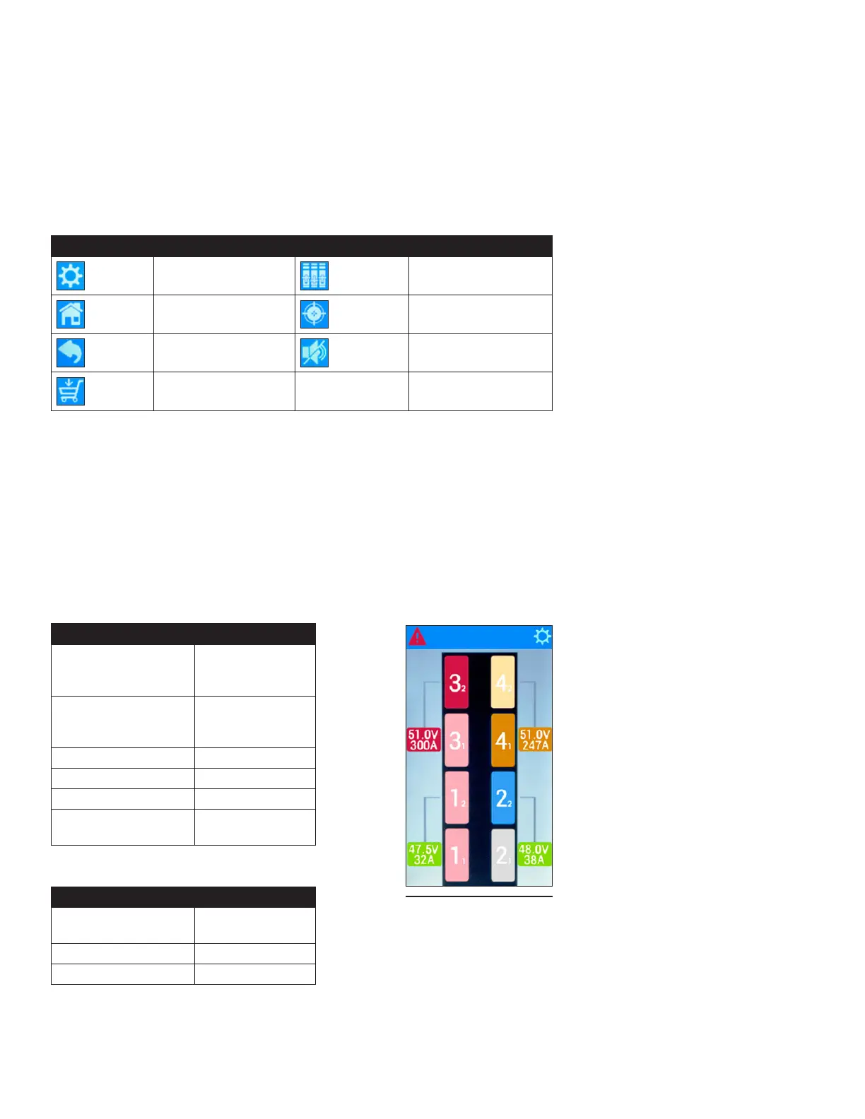
6.2 6.2 AlarmsAlarms
Each type of alarm is assigned a specic color. Normal operation for the
panel alarm status on the A-side of the BDFB is represented by a light shade
of red, while normal operation on the B-side is represented by the color blue.
The bus identication number is represented by the larger number shown on
the panel icon and the panel identication number for the corresponding bus
is represented by the smaller number. Bus voltage and amperage status is
displayed in the smaller colored icons shown next to the BDFB icon.
Table 17. Panel Alarm Status
COLOR STATUS
Light Red Normal
Operation
(A-Side)
Blue Normal
Operation
(B-Side)
Orange Minor Alarm
Light Orange Minor Alarm
Red Major Alarm
Light Gray Empty Panel
Position
Table 18. Bus Alarm Status
COLOR STATUS
Green Normal
Operation
Orange Minor Alarm
Red Major Alarm
Figure 43. Home
Screen (Quad -Bus
Conguration Shown)