3
4
×6×6
×2
×2 ×2×2 ×2×2 ×2×2
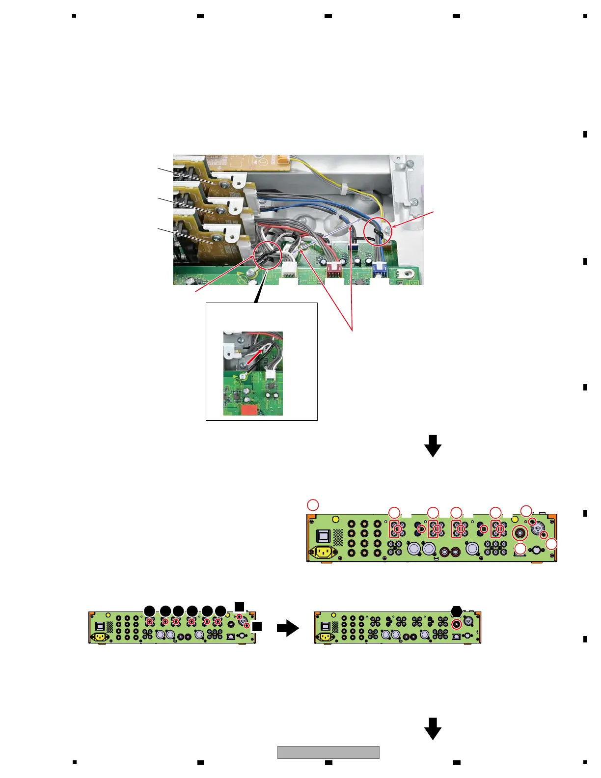
3 Remove the 8 Plug/PINs.
4 Remove the 6 screws.
(BPZ30P080FTB)
5 Remove the one washer and one nut.
(DEC2920, NKX2FNI)
6 Remove the 2 screws.
(PPZ30P080FTB)
3 3 3
6
5
6
• Rear view
SNRT3 Assy
SNRT2 Assy
SNRT1 Assy
Perform the following connection and styling of the jumper wires between SNRT1, 2, 3 Assys and AIN Assy.
Confirm whether color of Jumper wires of SNRT1, 2, 3 and connector (CN4003, 4004, 4005) match as follows.
! SNRT1 f CN4003 : White
! SNRT2 f CN4004 : Red
! SNRT3 f CN4005 : Blue
CN4003
(White)
CN4003
(White)
CN4004
(Red)
CN4004
(Red)
CN4005
(Blue)
CN4005
(Blue)
g Jumper wires styling
Clamp the jumper wire (blue) from
the SNRT3 Assy with Cord clamper
in the fig.
Make styling so that each other's jumper wires
do not come in contact.
Clamp the jumper wire (white)
from the SNRT1 Assy with
Cord clamper in the fig.
1 2 3 4 5 6
Screw, Washer and Nut tightening order
1
2
Clamp the Cord clamper
to the direction of the arrow.
1