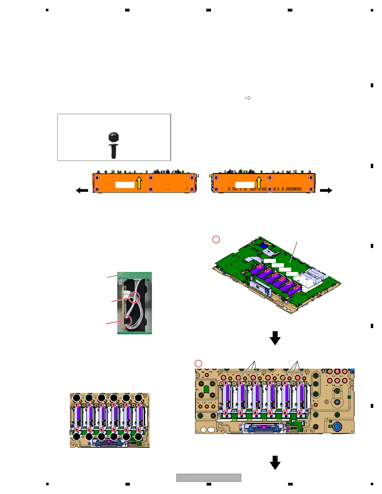
[4] Control Panel Section
[4-1] Channel fader Section
1 Disconnect the 6 connectors.
(CN8404, 8405, 8407, 8408, 8409, 8411)
2 Remove the 12 screws and then remove the
6 Channel fader Sections.
(BSZ20P040FTB)
Front Front
UCOM Assy
Channel fader SectionChannel fader Section
UCOM Assy
CN8411CN8411
CN8409
CN8409
CN8408
CN8408
CN8407
CN8407
CN8405
CN8405
CN8404
CN8404
Push upPush up Push upPush up
1
2
3
4
5
6
7
8
9
10 12
11
Screw tightening order
g Jumper wires styling
g Reference information
About Side panel
When repairing the substrate, it is not necessary to remove the Side panel.
If removed, reassemble while paying attention to the following points.
1. Assemble the Side panel to the product before fixing the Control panel.
However, do not fix the Side panel with screws at this state.
2. The Side panel is fixed after fixing the Front panel with screws.
When fixing the Side panel, perform it while pushing it up in the direction of l
.
And, be sure to use the specified screws.
Put the jumper wire
to the hook.
Cable of the UCOM side
passes the top.
DBA1290
Caution :
Be sure to use the following screw at the
reassembling!
1
×6×6
2
×12×12
• Bottom view
 Loading...