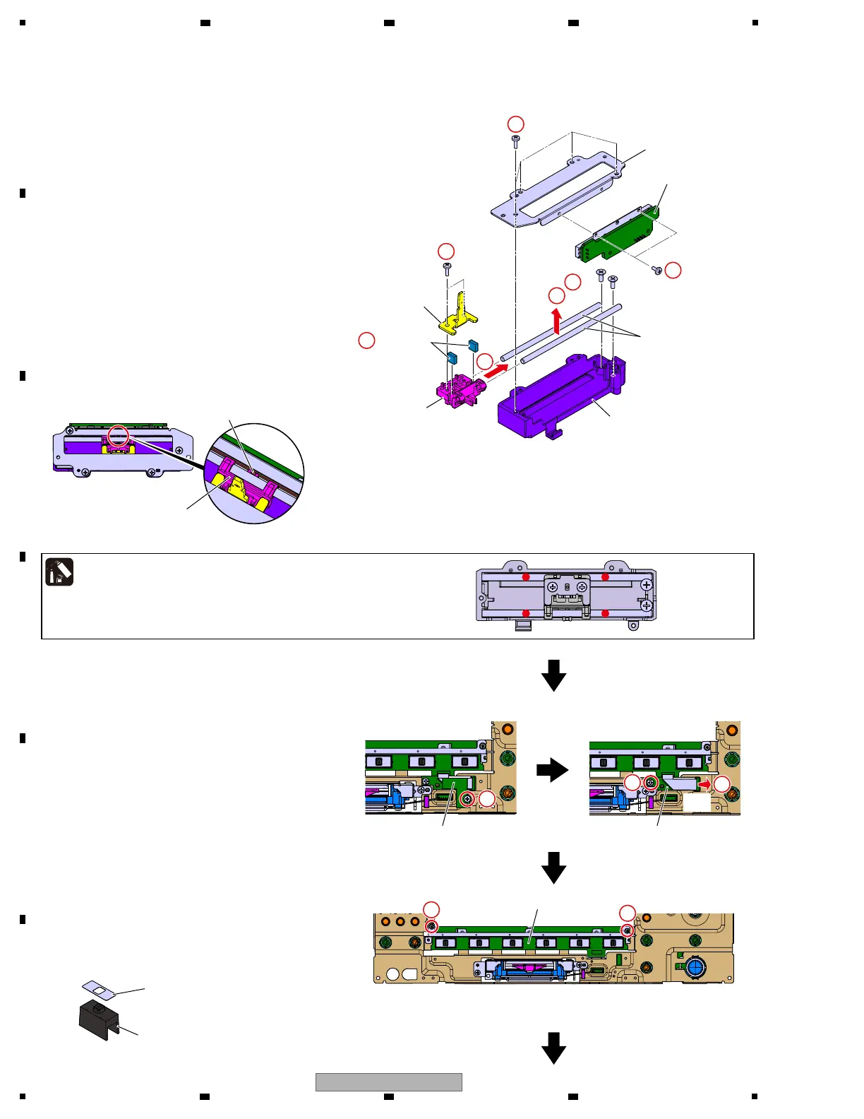
[4-2] CHF1 to CHF6 Assys
1 Remove the 4 screws and then remove the
Cover with PC board.
(BPZ20P060FTC)
2 Remove the 2 screws and then remove the
CHF* Assy.
(BSZ20P040FTB)
3 Remove the 2 screws.
(CPZ26P080FTC)
4 Remove the Slider Section.
5 Remove the 2 Guide shafts VK1.
6 Remove the 2 screws and then remove the
Lever plate.
(BPZ20P060FTC)
7 Remove the 2 Cushions.
[4-3] CRFSW Assy
1 Remove the one screw and then remove the
SWTOP Assy.
(BBZ30P060FTC)
2 Disconnect the one FFC.
(CN7603)
3 Remove the one screw and then remove the
SWBTM Assy.
(BBZ30P060FTC)
4 Remove the 2 screws and then remove the
CRFSW Assy.
(DBA1451)
CHF* Assy
Cover
Guide shaft VK1
Holder
SWTOP Assy SWBTM Assy
CRFSW Assy
Slider
Slider
Cushion
Lever plate
1
×4×4
2
×2×2
6
7
×2×2
3
4
5
×2×2
Lubricating oil
(GEM1107)
Note:
Greasing must be performed at a total of 4 points, 2 points
each for the upper and bottom places of each shaft.
(0.01 to 0.02 g per point × 4 points)
After applying grease, move the slider base back and forth
from one end to the other for approximately 30 strokes, in order
to fully spread the grease.
g Locations of grease application
1
3
4
4
2
CN7603
(BFXB)
CN7603
(BFXB)
Slide SW Cap (W)
Sheet
Nonreusable to fix it
with DS tape.
g Notes on assembling
Lever of VR
Confirm that a lever of VR is inserted in a slit of
the Slider.
g Notes on assembling
 Loading...