Hydraulic circuit diagram
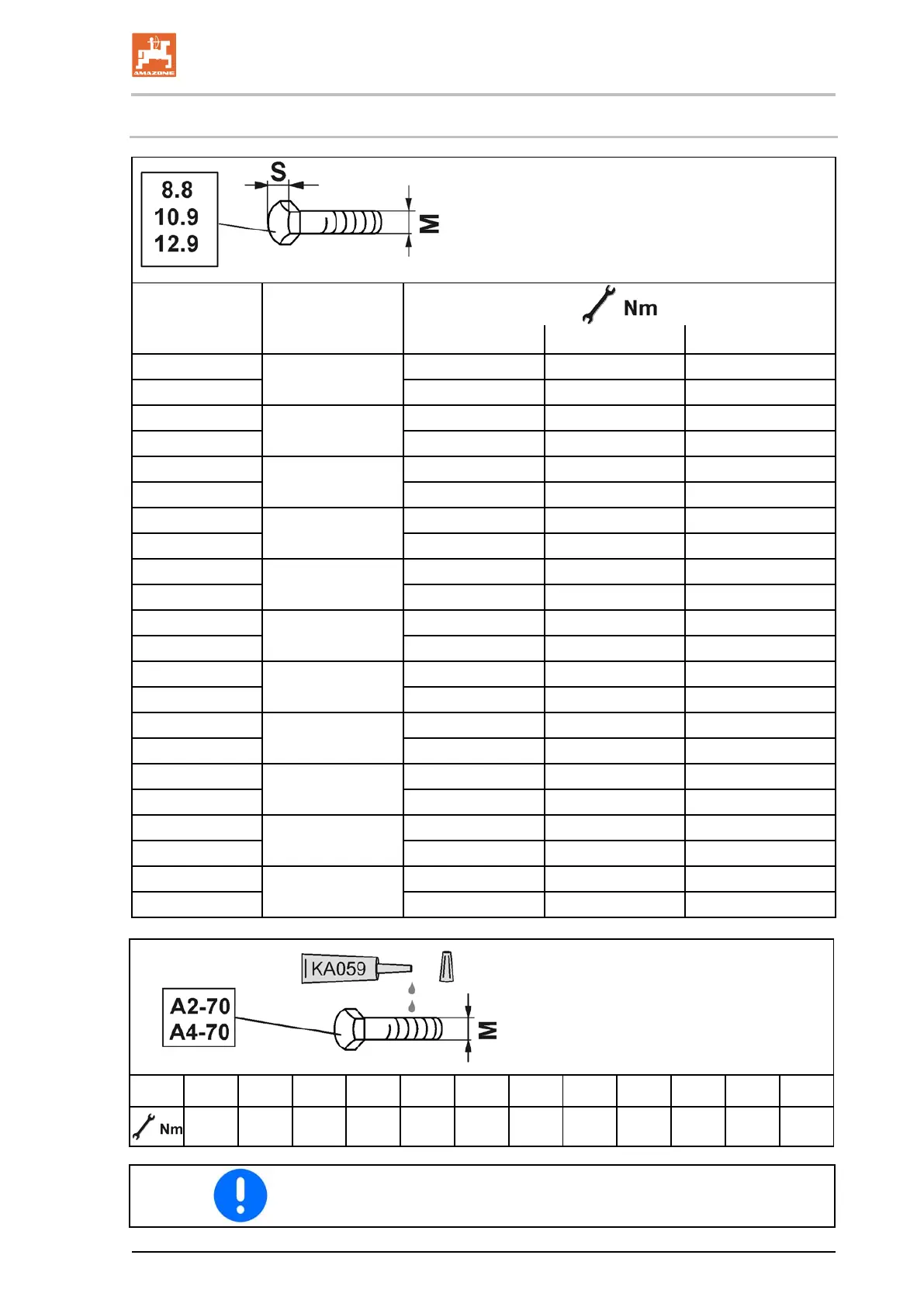
13.1 Screw tightening torques
M 8
13
25 35 41
M 8x1 27 38 41
M 10
16 (17)
49 69 83
M 10x1 52 73 88
M 12
18 (19)
86 120 145
M 12x1,5 90 125 150
M 14
22
135 190 230
M 14x1,5 150 210 250
M 16
24
210 300 355
M 16x1,5 225 315 380
M 18
27
290 405 485
M 18x1,5 325 460 550
M 20
30
410 580 690
M 20x1,5 460 640 770
M 22
32
550 780 930
M 22x1,5 610 860 1050
M 24
36
710 1000 1200
M 24x2 780 1100 1300
M 27
41
1050 1500 1800
M 27x2 1150 1600 1950
M 30
46
1450 2000 2400
M 30x2 1600 2250 2700
M
M4 M5 M6 M8 M10 M12 M14 M16 M18 M20 M22 M24
2,4 4,9 8,4 20,6 40,7 70,5 112 174 242 342 470 589
Coated screws have different tightening torques.Note special infor-
mation for tightening torques in chapter Maintenance.
Cenius 03 BAG0144.5 10.19
79