M470039-01 REV-F Page 49
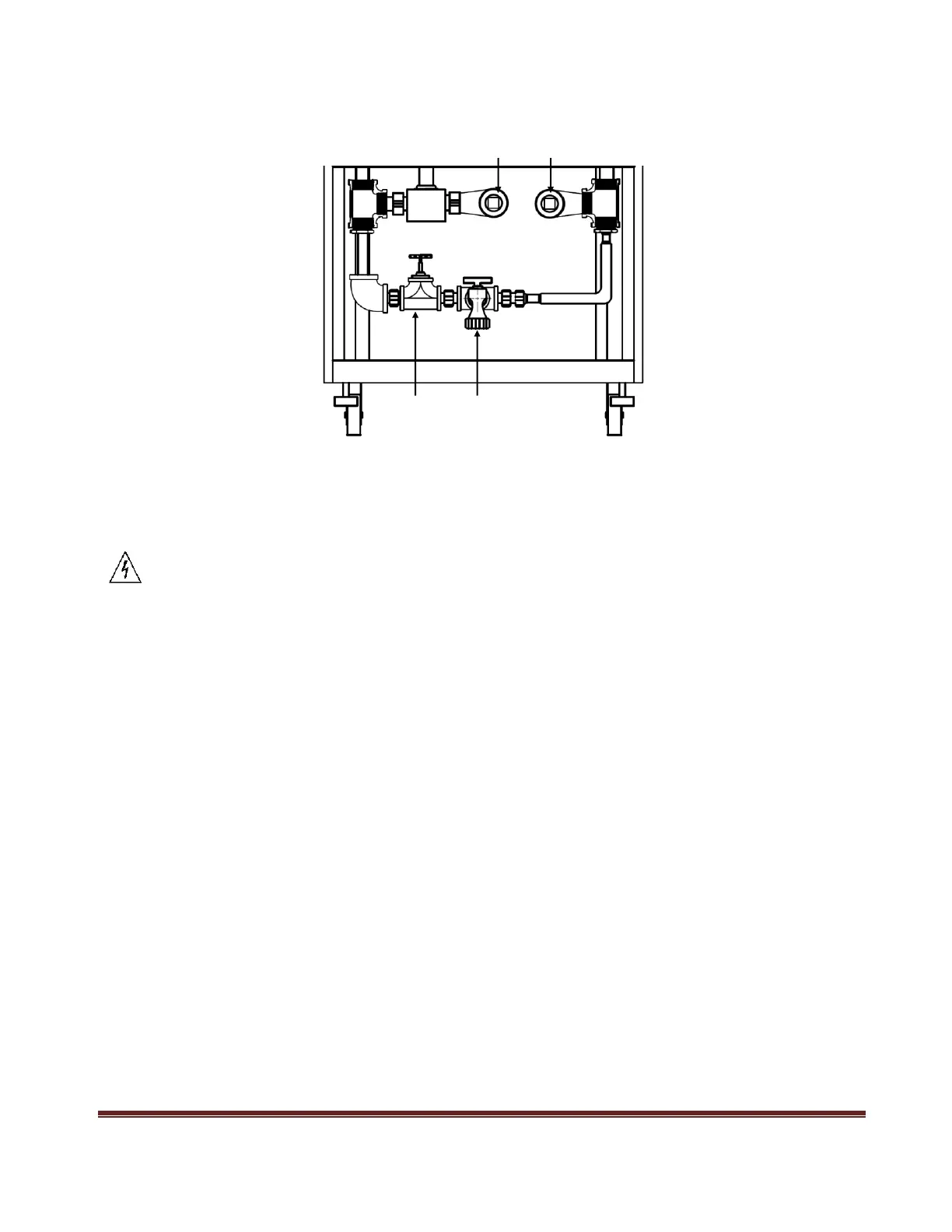
REAR PANEL INLET AND OUTPUT PIPE INSTALLATION (For PLW Rack/Cabinet Only)
For PLW models greater than 4U height, unit will be ship in a cabinet with a pre-installed manifold system. Rear Panel
diagram above illustrates positions of the cooling water inlet and outlet pipe as well as the drain faucet and pressure
release faucet. Before filling the Load Bank with water, carefully read the following paragraphs for correct flow rate,
water flow direction, and water pressure.
JJJJJJ
Ensure the correct water flow direction and flow rate is set. Improper settings will extensively affect the power
module heat dissipation capability. At all time, do not exceed the inlet water flow pressure limits and water pipe
pressure specifications in order to prevent leakage or water pipe rupture.
Refer to the specification for pipe size, proper water flow rate and pressure limit for inlet water.
INLET WATER
Refer to attached drawing of Rear Panel diagram for the position of the inlet water pipe located in the bottom left center
of the cabinet. Properly tighten the pipe with the correct wrench and do not over tighten the pipe causing damage to the
threads.
Note: 150 micron filtration is recommended.
OUTLET WATER
Refer to attached drawing of Rear Panel diagram for the position of the outlet water pipe located in the bottom right
corner of the cabinet. Properly tighten the pipe with the correct wrench and do not over tighten the pipe causing damage
to the threads.
WATER PRESSURE
Before applying water to the Load Bank, separately turn-off the drain faucet (clockwise direction) and pressure release
faucet (clockwise direction). Gradually let the water flow and check for any leaks in the pipe and lines. If any leaks are
found, relieve the pressure and tighten the pipe connector immediately with the proper tool.
Note: The load must have water flow in order to work properly and the water pressure must be less than 80 PSI.
 Loading...