Sorensen DCS Series 1kW and 1.2kW Supplies Installation and Operation
M362500-01 Rev K 2-17
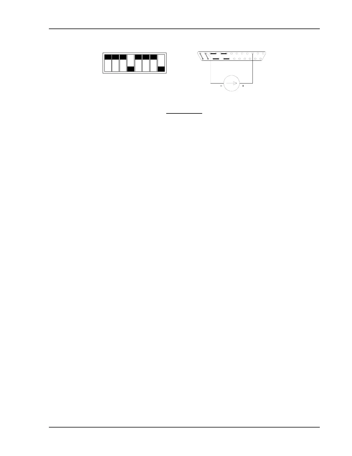
SW1-1
SW1-2
SW1-3
SW1-4
SW1-5
SW1-6
SW1-7
SW1-8
CLOSED
CONNECTOR J3
0-1mA
1312
25
3 1
14
OPEN
Switch SW1
SW1-1 Off (Open)
SW1-2 Off (Open)
SW1-3 Off (Open)
SW1-4 On (Closed)
SW1-5 Off (Open)
SW1-6 Off (Open)
SW1-7 Off (Open)
SW1-8 On (Closed)
Switch SW1 and Connector J3 Configuration
for 0-1mA Current Source OVP Programming
(J3 sense line, voltage control and current control jumpers shown set for local operation)
2.10 Remote ON/OFF
This feature is useful in test applications requiring remote ON-OFF control of the output. The
remote ON-OFF control circuit uses either a TTL compatible or a 12-250 Vac (or 12-130 Vdc)
input to remotely control (disable or enable) the power supply output. For TTL operation, a logic
level signal between pins 14 (positive) and 2 (return) of connector J3 determines the output
conditions:
TTL LOW = OUTPUT ON
TTL HIGH = OUTPUT OFF
For AC or DC operation, an input of 12-250 Vac (or 12-130 Vdc) between pins 1 (positive for DC
input) and 2 (return) of connector J3 will disable the output of the supply.
A red LED on the front panel indicates when the shutdown circuit is activated. The input lines
are optically isolated and can therefore be accessed by circuits with a voltage differential of up
to 600 Vdc.
2.10.1 Remote ON/OFF by Contact Closure
An external relay may be used to operate the ON/OFF control circuit as follows. Connect one
side of a normally open relay to pin 15 of connector J3 (+12V). Connect the other side of the
relay to pin 14 (TTL Shutdown). Also connect J3 pin 2 (Shutdown return) to pin 6 (Ground).
Using this configuration, the power supply will be OFF when the relay coil is energized and ON
when the relay is de-energized.

 Loading...

