Sorensen DCS Series 1kW and 1.2kW Supplies Installation and Operation
M362500-01 Rev K 2-23
2.12 Remote Monitoring and Status Indicators
Readback signals for remote monitoring of the output voltage and current are available at
connector J3 on the rear of the unit. A 0-5V (uncalibrated) signal between pins 19 (positive)
and 12 (negative) represents 0-100% of the rated output voltage. A 0-5V (calibrated) signal
between pins 7 (positive) and 12 (negative) represents 0-100% of the rated output current. The
offset and gain of the current readback signal may be adjusted through holes in the cover of the
unit (see Section 4.4 Calibration for location of adjusting holes).
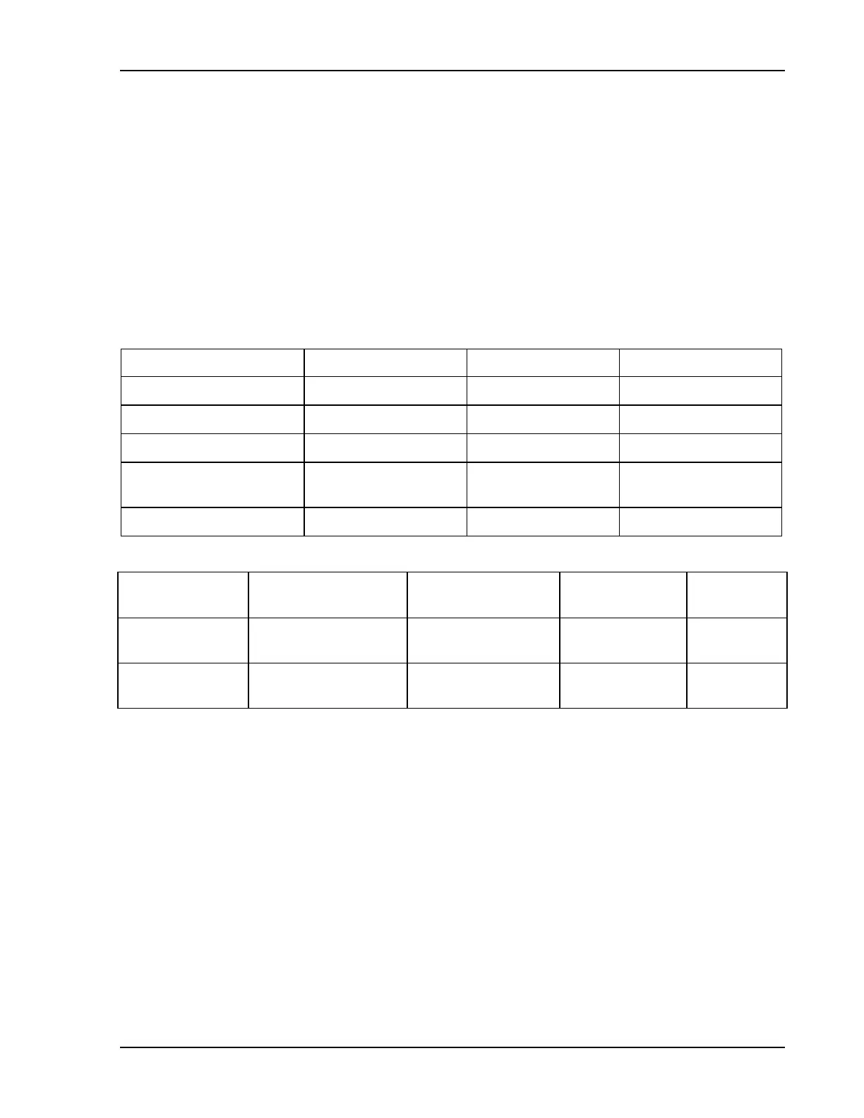
Status indicators for thermal shutdown, OVP operation, remote programming and operating
mode are also available through the J3 connector. The table below lists the various signals, the
J3 connector pins where they are available, the approximate magnitude of the signal (measured
with respect to pin 6 of connector J3) and the source impedance through which the signal is fed.
Indicator Signal J3 Connector Pin Signal Voltage Source Impedance
Thermal Shutdown 18 +10V
750Ω
OVP Circuit Activated 17 +9V
750Ω
Remote Programming 4 +10V
750Ω
Voltage Mode
Operation
5 +10V
750Ω
Current Mode Operation
5 -3V
750Ω
Monitor Signal J3 Connector Pin Jumper Selection
Output Signal
Range
Source
Impedance
Output Voltage
19 (+)
6 (RTN)
JP1
OUT
IN
0–5V
0–10V
100Ω
Output Current
7 (+)
6 (RTN)
JP2
OUT
IN
0–5V
0–10V
100Ω

 Loading...

