Sorensen DCS Series 1kW and 1.2kW Supplies Installation and Operation
M362500-01 Rev K 2-21
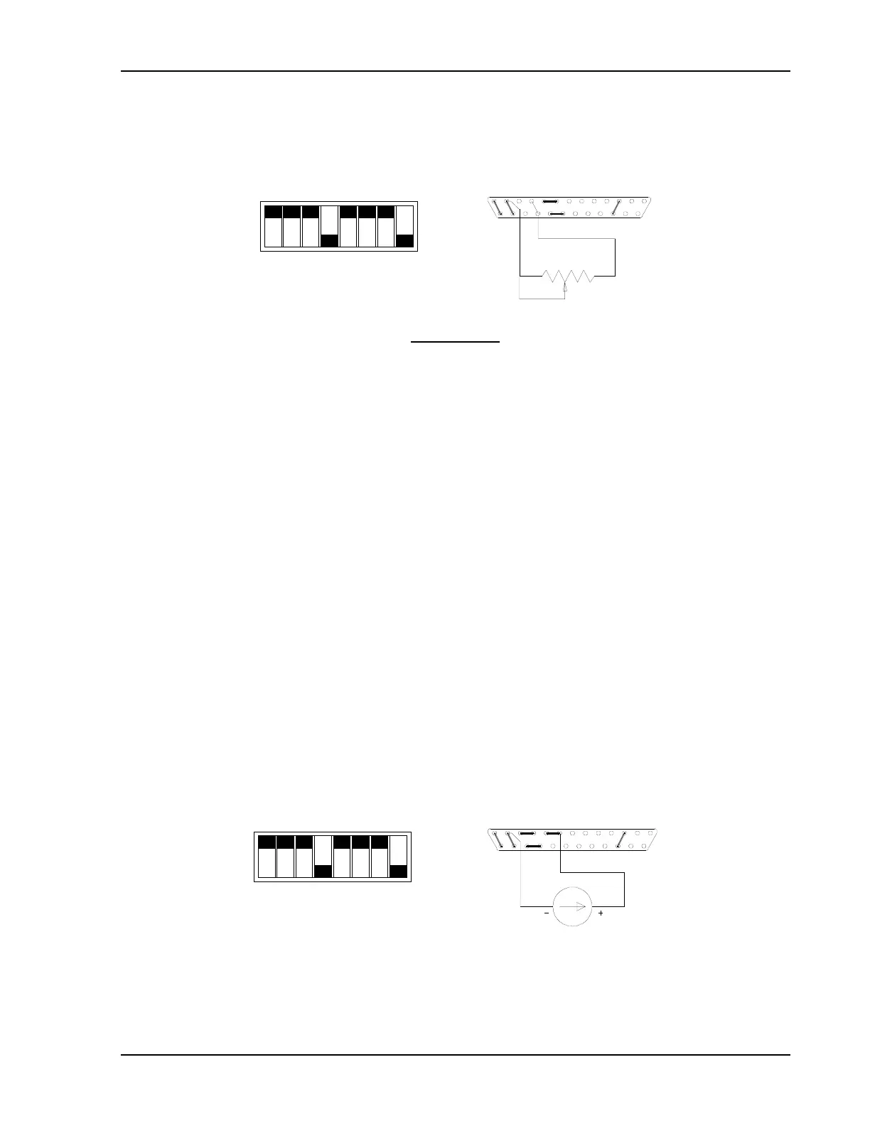
Connect pins 10 and 22 to the counterclockwise end of the 5k potentiometer and connect the
tap and clockwise end of the potentiometer to pin 12. Adjusting the tapped resistance from 0-5k
will vary the current limit from 0-100% of the rated output.
CLOSED
CCW
1312
25
10
22
1
14
OPEN
Switch SW1
SW1-1 Off (Open)
SW1-2 Off (Open)
SW1-3 Off (Open)
SW1-4 On (Closed)
SW1-5 Off (Open)
SW1-6 Off (Open)
SW1-7 Off (Open)
SW1-8 On (Closed)
Switch SW1 and Connector J3 Configuration
for Resistive Programming of the Output Current Limit
(J3 sense line, OVP and voltage control jumpers shown set for local operation)
2.11.3 Programming With an External Current Source
The output voltage and current limit can be programmed using an external 0-1mA current
source.
To program the output voltage, set the front panel voltage control to maximum, set switch
SW1-3 open (default factory setting) and remove the jumper between pins 20 and 21 of
connector J3. Connect the external current source between pins 8 (positive) and 12 (return) of
connector J3. Varying the current source from 0-1mA will vary the output voltage from 0-100%
of the rated output.
SW1-1
SW1-2
SW1-3
SW1-4
SW1-5
SW1-6
SW1-7
SW1-8
CLOSED
CONNECTOR J3
0-1mA
1312
25
8 1
14
OPEN
Switch SW1 and Connector J3 Configuration
for 0-1mA Current Programming of the Output Voltage
(J3 sense line, OVP and current control jumpers shown set for local operation)

 Loading...

