Installation and Operation Sorensen DCS Series 1kW and 1.2kW Supplies
2-18 M362500-01 Rev K
If a normally closed relay is substituted for the normally open relay in the configuration
described above, the power supply will be ON when the relay coil is energized and OFF when
the relay is de-energized.
2.11 Remote Programming of Output Voltage and
Current Limit
The output voltage and current limit of the power supply can be remotely programmed through
the rear panel J3 connector using external voltage sources, current sources and
resistances. Switch SW1 on the A2 printed circuit board controls the programming as
diagrammed below. When the supply is controlled by remote programming, the green
REMOTE led on the front panel is illuminated.
SW1-1
SW1-2
SW1-3
SW1-4
SW1-5
SW1-6
SW1-7
SW1-8
CLOSED
SELECTS
REMOTE CURRENT LIMIT
5V OR 10V PROGRAMMING
OF
SELECTS REMOTE
RESISTIVE OVP
PROGRAMMING SCALE
SELECTS
REMOTE VOLTAGE LIMIT
5V OR 10V PROGRAMMING
OF
NOT USED
NOT USED
Switch SW1 and Functions
Note: To set SW1, shut the unit off, disconnect the AC source, and remove the cover. Make
the desired switch settings, reinstall the cover, and reconnect the unit to its AC source.
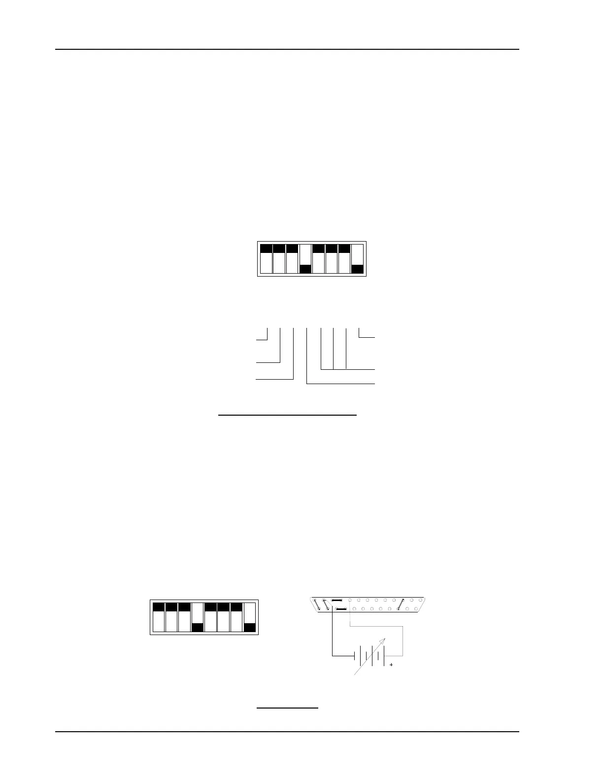
2.11.1 Programming With External Voltage Sources
The output voltage can be programmed using either a 0-5 Vdc or 0-10 Vdc external voltage
source. To program the output voltage with a 0-5 Vdc source, set switch SW1-3 open (default
factory setting) and remove the jumpers connecting pins 8 to 9 and 20 to 21 on connector J3.
Connect the external source between pins 9 (positive) and 12 (return). Varying the external
voltage from 0-5V will cause the output to vary from 0-100% of rated output.
CLOSED
1312
25
9 1
14
OPEN
Switch SW1

 Loading...

